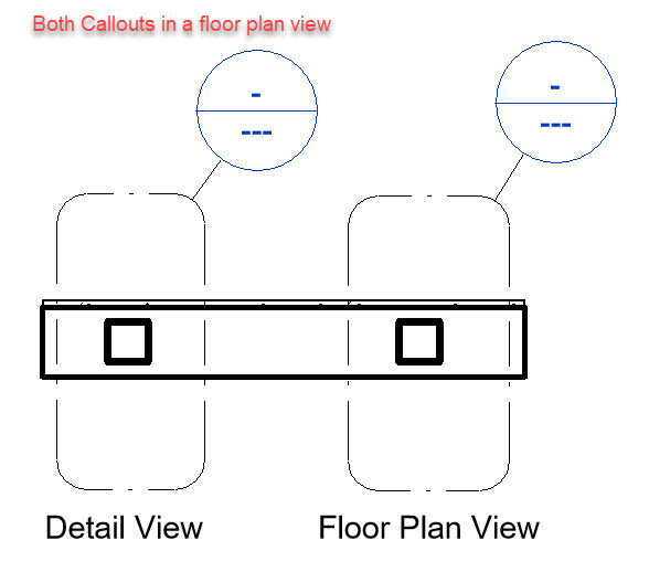
When we create a Callout within a plan view we can choose between Floor plan and Detail. A structural column that uses a negative offset won't show up when a wall exists in the same location when a Detail view type is used. It works fine in a Floor plan view type.
Here are some example images. The first one is showing the negative offset used. If the offset is zero then there is no graphical issue, the column shows up.
This image shows both callouts in the overall floor plan, Detail on the left and Floor on the right.
This is the Floor Plan Callout, column shows up as expected.
This is the Detail Callout, no column is visible.
This is the same Detail Callout but my cursor is hovering over the column and Revit sees it, highlights it despite not being visible. The wall is masking the column.
This is the same Detail Callout but the view is changed to use Wireframe and the column appears.
It boils down to the negative offset applied to the column. The graphics hierarchy does not respect the full height of the column and the wall element is drawn over the structural column. We can also get around the issue if we edit the column family and remove the option: Show family pre-cut in plan views.
Welcome to Steve Stafford's Blog ~ Revit OpEd = OPinion EDitorial ~ My view of things Revit, both real and imagined.
Monday, May 20, 2019
Wednesday, May 08, 2019
RevitForum.org Back
It appears to be restored via a new ISP and up and running again. Glad it's back!
...EDIT...some are saying it isn't fully set up at the new ISP yet...mileage may vary for a bit longer but it is on the way.
...EDIT...Site is still in transition to a new ISP, a message to that effect appears on the site until it is fully transitioned. (05/10/2019)
...EDIT...Site is UP, restored...aahhh
...EDIT...some are saying it isn't fully set up at the new ISP yet...mileage may vary for a bit longer but it is on the way.
...EDIT...Site is still in transition to a new ISP, a message to that effect appears on the site until it is fully transitioned. (05/10/2019)
...EDIT...Site is UP, restored...aahhh
Labels:
Forums,
Issues,
Posting,
RevitForum.org
Monday, May 06, 2019
Linked Details - 3rd Party Tool Options
This is an update to a much earlier post after getting a couple comments on that thread. These are three companies I'm familiar with that are providing solutions that contend with sharing details between projects and multiple model projects.
Revolution Design - Revit Workflow
26 Degrees Software - ViewAQC
Parallax Team - Parallax Linked Details
Check them out!
Revolution Design - Revit Workflow
26 Degrees Software - ViewAQC
Parallax Team - Parallax Linked Details
Check them out!
Tuesday, April 30, 2019
Revit Forum dot Org Not Working
It’s been about a week now where some of us can’t post/reply at the forum. I guess I’ll give up trying at this point. I can only spend so much time replying only to have the forum crash. Hopefully they’ll figure it out eventually. Maybe someone can tell me if/when that happens? Good luck!
Wednesday, April 24, 2019
Keynote Legends and Keynotes not Updating 2018.3
In Revit 2018.3.2.7 I am seeing and getting reports that keynote legends are not updating to show the current state of keynote tags visible in views. The existing workaround to force a refresh by turning on/off the Annotation Crop Boundary works but is entirely impractical to expect a team to open every sheet and do that task for each and every view on a sheet.
This past Knowledge Network post seems relevant. A portion of the text at that article suggests...
We really need this fixed ASAP!!
Workaround:
There are a few ways you could work around this behavior, and the best method will vary depending on the model geometry and number of affected tags. Here are a few options:
Temporary fixes (these will restore the display keynote tags, but future view changes will clear them again):
Temporarily adjust the location of the Cut Plane so that is above the affected elements (this will restore the value to the tags) and then restore the original cut plane location. Note: Some customers have noted that for views with dependent views, this process is required:
(Note: this may not work for some elements such as Duct; in that case, see the Non-temporary fix below.) Recreate the affected tags manually.
- Open the parent view and adjust the cut plane upward.
- open all sheets containing dependent views belonging to this parent view to refresh the keynote tags.
- move the cut plane back to its original position in the parent view.
Non-temporary fix (This will prevent future changes to the view from clearing the keynote tag): Adjust view or elements so that the cut plane is above the affected elements. (This could be done with a Plan Region.)
Labels:
bugs,
Complaints,
Issues,
Keynotes,
Legends,
Troubleshooting
Wednesday, November 28, 2018
Downloads Fixed - Some
I have been trying to carve out a little time here and there to fix the paths to downloads I've shared in the past. As of now the most requested stuff is fixed, the egress family and railing files. If you try to download something and hit a page not found warning, drop a comment in the post to bring it to my attention and I'll make it a priority.
Thanks for being patient - The mGmT...
Labels:
downloads,
Files,
Maintenance,
Sharing,
Troubleshooting,
Update
Wednesday, October 17, 2018
Reveal Elements - Hidden Viewport
The other day I was looking at a sheet a user reported it was impossible to select a floor plan view on. It seemed as though Revit did not see the view port on the sheet. People frequently pin views to make it a bit harder for other people to move them on a sheet accidentally. That will still allow a view port to be seen by Revit, it will still highlight as the cursor travels over it.
Then I thought of right-click Hide In View > Element. I used Reveal Elements and I could select the viewport. Using that tool does not hide what is visible in the view, it just disables the ability to select the view port.
Good? Bad? It isn't expected, well I didn't expect it.
Then I thought of right-click Hide In View > Element. I used Reveal Elements and I could select the viewport. Using that tool does not hide what is visible in the view, it just disables the ability to select the view port.
Good? Bad? It isn't expected, well I didn't expect it.
Monday, October 08, 2018
Change a System Parameter from Type to Instance - Not Length
It is fairly common knowledge that we can change a built-in parameter like Width from Type to Instance by going through the side door, selecting a dimension assigned to the parameter and changing it to Instance on the ribbon (see the image).
Kurt Thompson wrote to me to share how he gets around this issue when the parameter isn't something a dimension can be associated with. Specifically he was referring to a thread at the Autodesk User Forums where a member (electrical focus) was asking Autodesk to change the default parameters for Mains (instance), MCB Rating (type) and Subfeed Lugs (type). They argue that each parameter should be the opposite of the current configuration based on how the information is really dealt with (not that he needs me to, but I agree with him).
Kurt writes:
Kurt Thompson wrote to me to share how he gets around this issue when the parameter isn't something a dimension can be associated with. Specifically he was referring to a thread at the Autodesk User Forums where a member (electrical focus) was asking Autodesk to change the default parameters for Mains (instance), MCB Rating (type) and Subfeed Lugs (type). They argue that each parameter should be the opposite of the current configuration based on how the information is really dealt with (not that he needs me to, but I agree with him).
Kurt writes:
"To change a System Type parameter to Instance...(specific to the mentioned thread)Thanks Kurt!
Create a Shared Parameter built exactly like the built-in parameter you need to change but make it Instance instead of Type. Starting out with a Generic Model family, add the new parameter. Now assign the family to the category Electrical Equipment, Revit will replace the shared parameter with the built-in parameter but it will retain the Instance (or Type) property setting from the shared parameter. Give it a try."
Friday, September 28, 2018
Color Fill Calculation Failed is Back
This warning appeared quite a bit with Revit 2016 and patched in subsequent updates.

I've clicked Restart to no joy and I've submitted the error. I've done the Edit Color Scheme and Cancel process described for Revit 2016 with no joy either. Hopefully it will get sorted out again.

I've clicked Restart to no joy and I've submitted the error. I've done the Edit Color Scheme and Cancel process described for Revit 2016 with no joy either. Hopefully it will get sorted out again.
Labels:
bugs,
Calculations,
Color Fill,
Complaints,
Errors,
Issues,
Patch,
Troubleshooting,
Warnings
Thursday, September 27, 2018
Property Boundary and Coordinate Data - Dynamo
Alternate title: Mr. Revit OpEd finally does something (tho basic) with Dynamo!
I used this problem as an excuse to dig into Dynamo a bit. I created the attached graph to read a text file with coordinate values, one line per X,Y,Z values.
The text file format is very basic, it looks like this:
I created a 3D cylinder and model lines to form a target symbol family, 3D and fairly large so I could see it anywhere in the model. The graph places a target family at each coordinate location. Before running the graph, I assigned the Project Units for Length to Meter. Then I ran (manual) the Dynamo graph to place the target families. The last step was to start the Property Line tool and sketch the property boundary segments from target to target, which looks like this.
It was necessary to move the points closer to Revit's origin so they were not so far away, since Revit hates that. After doing that, I moved the Survey Point (not clipped) to one corner of the property (target family location) and then used Specify Coordinates at Point at that location using the coordinate values for that corner. This will allow me to export the result to DWG, if necessary. I also created a specific Spot Coordinate family type so I could identify some or every target location and make sure each reports the correct coordinates, double checking my work so to speak.
I probably spent a couple hours on this, mostly trying to get my head wrapped around which nodes in Dynamo to use. The next time I'll be twice as fast!
The text file format is very basic, it looks like this:
I created a 3D cylinder and model lines to form a target symbol family, 3D and fairly large so I could see it anywhere in the model. The graph places a target family at each coordinate location. Before running the graph, I assigned the Project Units for Length to Meter. Then I ran (manual) the Dynamo graph to place the target families. The last step was to start the Property Line tool and sketch the property boundary segments from target to target, which looks like this.
It was necessary to move the points closer to Revit's origin so they were not so far away, since Revit hates that. After doing that, I moved the Survey Point (not clipped) to one corner of the property (target family location) and then used Specify Coordinates at Point at that location using the coordinate values for that corner. This will allow me to export the result to DWG, if necessary. I also created a specific Spot Coordinate family type so I could identify some or every target location and make sure each reports the correct coordinates, double checking my work so to speak.
I probably spent a couple hours on this, mostly trying to get my head wrapped around which nodes in Dynamo to use. The next time I'll be twice as fast!
Wednesday, September 26, 2018
Links in Posts are Broken
An update to my company site has broken links to the files I've shared in posts throughout the history of my blog posts. Oh joy! I apologize for the inconvenience while I work through those to restore their paths.
Labels:
Blog Info,
Blog Posts,
downloads,
Info,
Status,
Troubleshooting,
Update,
URL
Thursday, September 20, 2018
Troubleshooting - Start an Email or Forum Post
I find it helpful to resolve an issue by starting to write an email or forum post (or a blog post) to ask for help or complain about it. Trying to write an explanation for what is happening so someone else might be able to help me focuses my thoughts. Very often I find it isn't necessary to finish writing.
The answer presents itself during the writing.
Next time you're puzzling over something, consider writing down what you think is wrong and the solution may arrive as you type.
Worth mentioning that a short break can also help a lot. Grab a beverage, talk to someone else, or stretch your legs; or all the above. The change gives you chance to work on the problem in the background of your attention.
Labels:
Advice,
Issues,
Problems,
Suggestions,
Support,
Tips,
Tricks,
Troubleshooting
Wednesday, September 19, 2018
Moving a Viewport Error - Disjoin
The Move tool offers us an option called Disjoin. When it is used Revit deletes the original and creates a new element at the new location. That isn't obvious to us but if you examine the GUID (ID's of Selection) you'll find it has a new GUID after the Move is complete.
The option is sticky, we have to remember to disable it when we use the Move tool again. When we are working on sheets and adjusting views we now have an opportunity to run into a confusing error message.
If you run into this or people you support do, just remember to Disable da Disjoin.
The option is sticky, we have to remember to disable it when we use the Move tool again. When we are working on sheets and adjusting views we now have an opportunity to run into a confusing error message.
If you run into this or people you support do, just remember to Disable da Disjoin.
Per a comment: My previous post on re Disjoin.
Friday, September 07, 2018
Post Echo - Units - Accuracy - Tolerance
I saw David Baldacchino's tweet yesterday sharing a link to a blog post for another software product called FME from Safe Software. The article goes into detail more related to their own product naturally but it does describe the math and computer problems that developers deal with. I found it quite interesting as well as confirming much of what I'd read and been told in the past.
Have a look! It's titled: "FME 2018 Infinity War: How Automatic Tolerance Defeats Infinite Precision without a Snap – but with Anchored Vertices!"
Wednesday, September 05, 2018
Wish - Release Type Catalogs after Loading a Family
Revit needs to release the Type Catalog files after loading a family that use them.
That message makes the process of updating a type catalog tedious at best if you have to close Revit completely to release it so it can be edited, very inefficient. There was a brief period of time when Revit did release the file as it should, but that ended with 2018 if I recall correctly.
Tuesday, September 04, 2018
Resizable Dialogs in Revit 2019 - Not Noteblock Schedules
Hey! When you were making more dialog boxes re-sizable you missed one! It's really hard to be sure I'm selecting the correct family with this dialog.
If not outright re-sizable, maybe put the Name field at the top and stretch out the list box underneath and make it at least as wide as the dialog?
Labels:
Complaints,
Critique,
Dialogs,
Features,
New Features,
New Release,
Resize,
Updates
Wednesday, August 22, 2018
Remember Linked Files Have Two Workset Parameters
I find this overlooked regularly. Each link has an Instance AND Type parameter called Workset. If we select a link (RVT) in the Project Browser we can see the Type parameter for workset, even if the link isn't loaded.
If we right-click and choose Select All Instances > In Entire Project we can see the Instance parameter value, unless there is more than one instance (copies of the link).
The best way to ensure that both parameter values are assigned to the same workset is to make sure the Active Workset is set correctly first, before we link the file. If not then we have to check both values.
Why are there two parameters?
The Type parameter governs the existence of the link in the database while the Instance parameter governs the actual instance you can see in the model views. The linked file can be copied, for example House Design A can be copied so we can show that it will be located on several lots within a development, each likely oriented differently.
The instance parameter allows us to assign each copy to a unique workset while the Type parameter affects all of the copies. That means closing the workset assigned to the Type parameter will close all of the copies of the link, none of them will be visible.
If we close the workset assigned to just one copy then only that linked file won't be visible.
If we experience erratic issues with linked file visibility it is the first thing I check. I'm also in the habit of looking at all the linked files every time I get introduced to project. This also applies to other linked files (CAD,Point Cloud).
If we right-click and choose Select All Instances > In Entire Project we can see the Instance parameter value, unless there is more than one instance (copies of the link).
The best way to ensure that both parameter values are assigned to the same workset is to make sure the Active Workset is set correctly first, before we link the file. If not then we have to check both values.
Why are there two parameters?
The Type parameter governs the existence of the link in the database while the Instance parameter governs the actual instance you can see in the model views. The linked file can be copied, for example House Design A can be copied so we can show that it will be located on several lots within a development, each likely oriented differently.
The instance parameter allows us to assign each copy to a unique workset while the Type parameter affects all of the copies. That means closing the workset assigned to the Type parameter will close all of the copies of the link, none of them will be visible.
If we close the workset assigned to just one copy then only that linked file won't be visible.
If we experience erratic issues with linked file visibility it is the first thing I check. I'm also in the habit of looking at all the linked files every time I get introduced to project. This also applies to other linked files (CAD,Point Cloud).
Tuesday, August 21, 2018
Section Line Annotation Alignment
No, not the 2019.1 feature that allows us to use the Align tool on sections...
If you find yourself wondering why you don't the get the telltale dashed lines to help you line up section heads or tails check Visibility/Graphics for the view and make sure Lines are checked (visible). If the category is turned off, so too are they. These...
Check this...
If you find yourself wondering why you don't the get the telltale dashed lines to help you line up section heads or tails check Visibility/Graphics for the view and make sure Lines are checked (visible). If the category is turned off, so too are they. These...
Check this...
Friday, August 17, 2018
Cannot Publish Coordinates
I've run into this with a couple clients recently, this warning message appears:
Quirky work-around warning...
The error message is tied to linked files (DWG) that are actively changing. Revit would notice those links were different than the version it had a record of during a SwC, even though it does not reload links during a SwC. I imagine it takes note of the file date or something high level that defines the DWG in the database. The solution then was to reload those links before using SwC.
I have found since that it has been possible to avoid the warning if any linked DWG files are unloaded prior to using Publish Coordinates. In at least one situation we had to go through the steps above even when there were no DWG's linked/imported. Autodesk documentation says in some cases it can be associated with file corruption.
Quirky...
Quirky work-around warning...
- Building Model: Make sure you have a Local File for it (I save to my own PC)
- Site Model: Change the saved path to the Building's Central File to your own Local File instead
- Site Model: Publish Coordinates
- Site Model: SwC (should succeed and get a prompt to Save changes to the linked file)
- Site Model: Close
- Building Model: Open your existing Local File SwC (passes shared coordinate data to central)
- Building Model: Close
- Site Model: Reset the path for the Building to the central location
The error message is tied to linked files (DWG) that are actively changing. Revit would notice those links were different than the version it had a record of during a SwC, even though it does not reload links during a SwC. I imagine it takes note of the file date or something high level that defines the DWG in the database. The solution then was to reload those links before using SwC.
I have found since that it has been possible to avoid the warning if any linked DWG files are unloaded prior to using Publish Coordinates. In at least one situation we had to go through the steps above even when there were no DWG's linked/imported. Autodesk documentation says in some cases it can be associated with file corruption.
Quirky...
Thursday, August 16, 2018
App Thoughts - Project Info Workset
Lately I find the Project Info workset is borrowed by someone inadvertently (okay me). As such, I wishfully imagine I could mash a button and find out if I've got that workset borrowed based on selecting a project folder and it checking each of the project files it finds. Being able to browse through projects on Revit Server would be boss too. If it could relinquish any instances if finds for me that would be really boss.
I guess I'll have to wander off to the Dynamo salt mines to see if any of it's possible.
As for why this happens...in my case it is related to Publish Coordinates. That's the only operation Revit permits us to alter a linked file; alter and save changes to a file we don't have open in the active session.
At the moment I think it happens when the process fails to complete properly. However it has happened too on occasion when I was convinced it worked. I have some reservations about Revit Server too. I've noticed a higher proportion of projects not being able to use Publish Coordinates when the files are available via Revit Server. Which reminds me I've got a post in drafts about resolving a Can't Publish Coordinates situation...brb.
Casting numerous aspersions with only clues to base them on...not very scientifical of me eh?
I guess I'll have to wander off to the Dynamo salt mines to see if any of it's possible.
As for why this happens...in my case it is related to Publish Coordinates. That's the only operation Revit permits us to alter a linked file; alter and save changes to a file we don't have open in the active session.
At the moment I think it happens when the process fails to complete properly. However it has happened too on occasion when I was convinced it worked. I have some reservations about Revit Server too. I've noticed a higher proportion of projects not being able to use Publish Coordinates when the files are available via Revit Server. Which reminds me I've got a post in drafts about resolving a Can't Publish Coordinates situation...brb.
Casting numerous aspersions with only clues to base them on...not very scientifical of me eh?
Wednesday, August 15, 2018
Project Units Matter - Specify Coordinates at Point
When we use the Specify Coordinates at Point (SPaC) it is possible that the units in use will affect your results. For example, this project is using Feet and Fractional Inches (FaFI) but for SPaC to match the available survey info it was changed to Decimal Inches (DI) with six decimal places. After using SPaC the units were returned to FaFI.
Some time later the elevation needed to be changed thus causing us to revisit using SPaC. The following image shows the original values used for SPaC.
Leaving the Project Units assigned to FaFI resulted is this subtle change to the coordinate values.
When the units were revised to match the earlier DI settings the SPaC coordinates are not altered.
Shorter story, be careful with your unit settings when using SPaC.
Some time later the elevation needed to be changed thus causing us to revisit using SPaC. The following image shows the original values used for SPaC.
Leaving the Project Units assigned to FaFI resulted is this subtle change to the coordinate values.
When the units were revised to match the earlier DI settings the SPaC coordinates are not altered.
Shorter story, be careful with your unit settings when using SPaC.
Tuesday, August 14, 2018
Move to Room - Element ID - Review Warnings
If we use Review Warnings often enough, and we should be, we'll run into this warning eventually.
Check the item and Click Show to have Revit try to find a view to show it in. Once it is selected we can either drag the Tag where it is suppose to go or Click the Show Related Warnings button on the ribbon to show the dedicated warning it has again.
When this warning is isolated like this the dialog includes the Move to Room button. An aside, is it amusing or worrisome that Revit seems to think the best way to fix warnings is to delete the offending element (via Delete Checked)? Regardless, Move to Room will resolve the issue whether we can see where the tag is meant to be or not.
Another way to tackle it from the Review Warnings dialog is to make a note of the Element ID referenced in the warning. Now we can then use the Select by ID tool. Enter the ID value and click OK.
This will select the tag, even if we're not in a view that it can be seen in, and then we can use the Show Related Warnings button on the ribbon again followed by the Move to Room button.
Check the item and Click Show to have Revit try to find a view to show it in. Once it is selected we can either drag the Tag where it is suppose to go or Click the Show Related Warnings button on the ribbon to show the dedicated warning it has again.
When this warning is isolated like this the dialog includes the Move to Room button. An aside, is it amusing or worrisome that Revit seems to think the best way to fix warnings is to delete the offending element (via Delete Checked)? Regardless, Move to Room will resolve the issue whether we can see where the tag is meant to be or not.
Another way to tackle it from the Review Warnings dialog is to make a note of the Element ID referenced in the warning. Now we can then use the Select by ID tool. Enter the ID value and click OK.
This will select the tag, even if we're not in a view that it can be seen in, and then we can use the Show Related Warnings button on the ribbon again followed by the Move to Room button.
Wednesday, April 11, 2018
What's New in Revit 2019
It's a teaser blog title. I have no idea what is in Revit 2019, or rather until I read THIS POST.
I'm looking forward to exploring the new features myself once I actually have time to download it.
As for not knowing what was coming like in the past. My access to their review program was screwed up last spring/summer and I haven't been able to log into the site ever since. I had someone looking in to it but their tech support efforts...well suffice it to write I haven't been able to log in. Bummer...
I hope you, dear reader, enjoy the new features in Revit 2019. I, like many of you, will get to experience them with fresh eyes!
Oh, Revit 2018.3 was released the other day too so look out for that update. As always, go slow with installation and rolling it out...make sure your existing projects are in a position to tolerate the potential for some issues before upgrading any projects. I wish you pleasant upgrades.
Double oh, a little birdie told me Paul Aubin and Bill Debevc (okay Bill told me) are going to do a podcast on the new features. Also Paul has a Lynda video on the new features.
I'm looking forward to exploring the new features myself once I actually have time to download it.
As for not knowing what was coming like in the past. My access to their review program was screwed up last spring/summer and I haven't been able to log into the site ever since. I had someone looking in to it but their tech support efforts...well suffice it to write I haven't been able to log in. Bummer...
I hope you, dear reader, enjoy the new features in Revit 2019. I, like many of you, will get to experience them with fresh eyes!
Oh, Revit 2018.3 was released the other day too so look out for that update. As always, go slow with installation and rolling it out...make sure your existing projects are in a position to tolerate the potential for some issues before upgrading any projects. I wish you pleasant upgrades.
Double oh, a little birdie told me Paul Aubin and Bill Debevc (okay Bill told me) are going to do a podcast on the new features. Also Paul has a Lynda video on the new features.
Tuesday, February 20, 2018
Copy Monitor - A Different Way?
Morning musing...
It's my observation that there is a prevailing mostly ambivalent attitude toward the Copy/Monitor (C/M) features. I've said before that I think the order of the tabs in the Options dialog are based on the likelihood that we'll use them. Specifically they are listed left to right: Levels, Grids, Columns, Walls and Floors.
C/M isn't hard to use but once it is in play we've got some new rules and warnings to contend with. The process depends on us identifying the elements we want to live in the C/M system. I understand the logic of that choice. Revit asks us to tell it what is important enough to us to engage the system.
Perhaps we need a completely different way to attack the problem? One that doesn't require the advance work. One that is more a reaction to work as it is created and shared, that merely exists.
I wonder if it would be more betterer if we could run a Level or Grid check as a process. The application would compare elements and compile a report, observations and differences. It could be something we read afterward or presented in a dialog for immediate action.
For example, it could just start with: "Hey Steve, there are 27 grids in your model and 30 in theirs. You should look at them." Take it slightly deeper, "Hey Steve, there are three grids that share the same name but are not in the same location."
Does it matter that they used to be in the same location and they aren't now? The application would have to start storing records for past results to do that but it could be useful to determine when or how things got off track. The rules or conditions that are interesting need to be defined.
This sort of element review and comparison doesn't have to be limited to the five that Copy/Monitor were designed for originally (overlooking the MEP elements that have been added in some fashion). It still requires two or more elements though; mine, yours and theirs. The redundancy is annoying but it does provide us with flexibility within our own models.
I imagine much of what I'm describing (and more) is possible via the API and Dynamo. It just needs someone to decide it is an interesting enough thing to do.
It's my observation that there is a prevailing mostly ambivalent attitude toward the Copy/Monitor (C/M) features. I've said before that I think the order of the tabs in the Options dialog are based on the likelihood that we'll use them. Specifically they are listed left to right: Levels, Grids, Columns, Walls and Floors.
C/M isn't hard to use but once it is in play we've got some new rules and warnings to contend with. The process depends on us identifying the elements we want to live in the C/M system. I understand the logic of that choice. Revit asks us to tell it what is important enough to us to engage the system.
Perhaps we need a completely different way to attack the problem? One that doesn't require the advance work. One that is more a reaction to work as it is created and shared, that merely exists.
I wonder if it would be more betterer if we could run a Level or Grid check as a process. The application would compare elements and compile a report, observations and differences. It could be something we read afterward or presented in a dialog for immediate action.
For example, it could just start with: "Hey Steve, there are 27 grids in your model and 30 in theirs. You should look at them." Take it slightly deeper, "Hey Steve, there are three grids that share the same name but are not in the same location."
Does it matter that they used to be in the same location and they aren't now? The application would have to start storing records for past results to do that but it could be useful to determine when or how things got off track. The rules or conditions that are interesting need to be defined.
This sort of element review and comparison doesn't have to be limited to the five that Copy/Monitor were designed for originally (overlooking the MEP elements that have been added in some fashion). It still requires two or more elements though; mine, yours and theirs. The redundancy is annoying but it does provide us with flexibility within our own models.
I imagine much of what I'm describing (and more) is possible via the API and Dynamo. It just needs someone to decide it is an interesting enough thing to do.
Labels:
Collaboration,
Columns,
Coordination,
Copy/Monitor,
Dept. of Opinion,
Features,
Floors,
Grids,
Ideas,
Levels,
Projects,
Tools,
Walls
Wednesday, January 17, 2018
Five Minutes with Shape Editing a Bay Roof
I posted this screencast in response to a thread at the Autodesk Forums. Figured I might as well share it here too. I used shape editing to create the bay roof condition shown in this image.
It's based on an image of a DWG roof plan that was shared in the original post in the discussion. The sketches of the main and bay roofs look like the following image. It also shows the sketched Split Line elements I added to make raising the bay ridge up easy.
Here's the screencast I created to post at the forums.
FWIW, I made the main roof partially transparent so I could see the walls more easily. In the video I commented about using the Two Cut Plumb setting with a 12" value. The Shape Editing disables that for the bay roof but it did start out with that setting in play so it all worked out as I intended even though I was confused about it at the time.
It's based on an image of a DWG roof plan that was shared in the original post in the discussion. The sketches of the main and bay roofs look like the following image. It also shows the sketched Split Line elements I added to make raising the bay ridge up easy.
Here's the screencast I created to post at the forums.
FWIW, I made the main roof partially transparent so I could see the walls more easily. In the video I commented about using the Two Cut Plumb setting with a 12" value. The Shape Editing disables that for the bay roof but it did start out with that setting in play so it all worked out as I intended even though I was confused about it at the time.
Labels:
Bay,
Editing,
Modelling,
Roof,
Shape Editing,
Techniques,
Tips,
Video
Thursday, December 21, 2017
Sketching Tangent Lines
A post based on my responses at the Autodesk Forum: Tangent Circle to Tangent Circle.
It could be easier...
I see Revit behaving this way, they regard the first point as ineligible to being tangent because it depends on the bearing of the line, With that assumption or bias, the first point is necessary to make a tangent condition possible. I can easily snap to a location on the circle (a pulley for example) that couldn't be tangent to the next pulley.
AutoCAD deals with this in a clever fashion (when we invoke the tangent snap) by fixing (changing) the first point to be tangent after the second point is placed. If we aren't careful with our second pick point (snap tangent too) the tangent line might end up on the opposite side of the pulley.
In contrast, Revit handles it naively, because it regards our first point as ineligible to tangents because it isn't considering this particular end result: "I want to draw a line tangent to two circles". AutoCAD appears to know this by virtue of snapping tangent for the first point so it can adjust the final bearing, and attachment to the circle, of the line.
To get around this naiveté, I place the first point on the pulley where it looks like it can be tangent, to my eye. The second point snaps to tangent with the icon. I return to the first point and grip/drag it away and back to let the snap icon appear, to fix it for tangent, just to see if I was close. If my guess wasn't accurate, it is now.
After reading a reply to my comments I did a quick sketch in AutoCAD and then did the same sketch in Revit using the same pulley sizes and offset from one another (see Footnote). The tangent lines have the same x/y properties for start and end as the AutoCAD version, that I made using its snap tangent.
This is the native DWG sketch and properties screen captures for each element.
This is same information but for the Revit drafting view exported to DWG. When I create an External Reference of the exported Revit drafting view it lands right on top of the native sketch. If you look really closely you'll see a value is slightly different in the Revit version. I think that might be my fault, sketching. Regardless, I think close enough is fair.
Footnote: Regarding a drafting view aligning with a DWG file after export: It might not be obvious but drafting views have an origin. To test that claim link a DWG, that has a marker at the WCS origin, into one and you'll see where the origin is. I did that before I did any sketching so I'd know how to place the pulleys in the same place. That made it possible to compare the tangent lines after exporting it to DWG.
Also the Start and End X/Y values are reversed. That's either just how Revit interprets the vector of each line segment or it's because of the direction I chose to sketch them in Revit. In AutoCAD I started at the smaller pulley. I didn't make sure to sketch in the same way in Revit, sloppy scientist.
It could be easier...
I see Revit behaving this way, they regard the first point as ineligible to being tangent because it depends on the bearing of the line, With that assumption or bias, the first point is necessary to make a tangent condition possible. I can easily snap to a location on the circle (a pulley for example) that couldn't be tangent to the next pulley.
AutoCAD deals with this in a clever fashion (when we invoke the tangent snap) by fixing (changing) the first point to be tangent after the second point is placed. If we aren't careful with our second pick point (snap tangent too) the tangent line might end up on the opposite side of the pulley.
In contrast, Revit handles it naively, because it regards our first point as ineligible to tangents because it isn't considering this particular end result: "I want to draw a line tangent to two circles". AutoCAD appears to know this by virtue of snapping tangent for the first point so it can adjust the final bearing, and attachment to the circle, of the line.
To get around this naiveté, I place the first point on the pulley where it looks like it can be tangent, to my eye. The second point snaps to tangent with the icon. I return to the first point and grip/drag it away and back to let the snap icon appear, to fix it for tangent, just to see if I was close. If my guess wasn't accurate, it is now.
After reading a reply to my comments I did a quick sketch in AutoCAD and then did the same sketch in Revit using the same pulley sizes and offset from one another (see Footnote). The tangent lines have the same x/y properties for start and end as the AutoCAD version, that I made using its snap tangent.
This is the native DWG sketch and properties screen captures for each element.
This is same information but for the Revit drafting view exported to DWG. When I create an External Reference of the exported Revit drafting view it lands right on top of the native sketch. If you look really closely you'll see a value is slightly different in the Revit version. I think that might be my fault, sketching. Regardless, I think close enough is fair.
Footnote: Regarding a drafting view aligning with a DWG file after export: It might not be obvious but drafting views have an origin. To test that claim link a DWG, that has a marker at the WCS origin, into one and you'll see where the origin is. I did that before I did any sketching so I'd know how to place the pulleys in the same place. That made it possible to compare the tangent lines after exporting it to DWG.
Also the Start and End X/Y values are reversed. That's either just how Revit interprets the vector of each line segment or it's because of the direction I chose to sketch them in Revit. In AutoCAD I started at the smaller pulley. I didn't make sure to sketch in the same way in Revit, sloppy scientist.
Wednesday, December 20, 2017
Dimension Inline and Dynamo
(Edit: If you download and apply an update to his Rhythm package after 1/17/2018 you'll have this node too)
From time to time I've heard people ask about putting the dimension value on the line (inline) instead of above the dimension line the way Revit prefers. The only way we can do it within Revit is to manually grip and drag the dimension value down to the line.
More recently I read a thread at the Autodesk Forum asking about this. The premise in their situation is that it is a significant roadblock to using Revit for one of their client's projects, it doesn't meet their drawing standard unless the dimensions are inline.
I was trading messages with Aaron Maller and mentioned it to him. Aaron was trading messages with John Pierson and a few minutes later I learned it is possible with Dynamo and a custom node. This morning he shared this with me, as well as replying to the thread. Nicely done John! We are sooo connected these days.
From time to time I've heard people ask about putting the dimension value on the line (inline) instead of above the dimension line the way Revit prefers. The only way we can do it within Revit is to manually grip and drag the dimension value down to the line.
More recently I read a thread at the Autodesk Forum asking about this. The premise in their situation is that it is a significant roadblock to using Revit for one of their client's projects, it doesn't meet their drawing standard unless the dimensions are inline.
I was trading messages with Aaron Maller and mentioned it to him. Aaron was trading messages with John Pierson and a few minutes later I learned it is possible with Dynamo and a custom node. This morning he shared this with me, as well as replying to the thread. Nicely done John! We are sooo connected these days.
Thursday, December 07, 2017
How Often to Synchronize with Central - SwC
Grist from a recent support conversation..."How often should we use Synchronize with Central (SwC)? We have some users doing it every minute."
Well....every minute seems a bit much...but...
The number of people actively working on a file affects the truth of the statement too. Every 30 minutes, for example, is too infrequent in my opinion. My own habit is to SwC as often as I complete any given task. I tend to take small bites, tasks that are 1-10 minutes, and SwC as soon as they are done.
More frequent SwC is less data transmission than every 30 minutes, potentially. Replacing or reloading a title block for 1,000 sheets is not a small task and probably ought to be done at lunch, advising people to create new local files afterward. Otherwise each sync will need to needlessly update each local file's copy of the sheet's title block too, for everyone. If that is done while they are all away they just inherit the new version of the project with their new local file.
It's all relative though because the transaction comparison between syncing that kind of change and closing a model and opening it later is subtle. In fact opening a file again might be slower, but reasonable, depending on how many people are involved. It can be justified though, especially if they are out of the project anyway such as out for lunch or after hours etc.
I think it is more important to be aware of other users also using SwC, than imposing a specific time requirement. When more than one person uses SwC at the same time Revit has to parse those changes and it does so, more or less, in a single threaded manner, not like a multi-thread OS (though they are improving that all the time) doing simultaneous tasks. It has to reconcile changes and move to others once it is satisfied it can finish successfully. The more people forcing Revit to do that at the same time the slower it gets for everyone. That's where the advice to schedule or increase the time between SwC came from. One client decided to build their own tool so users can see if someone is syncing. A button on their Quick Access Toolbar parked next to the SwC button is red when someone is syncing and green when nobody is. Green means go for it.
Any sort of "Every 30 minutes" rule is often an over simplification, a rule meant to be easy to implement. In practice it can be just as harmful as helpful. If I slip and go 60 minutes or longer then that starts to slow down SwC times for everyone else too. Pushing and pulling data through a pipe takes time, smaller chunks of data generally take less time and less time to reconcile with the model too.
I'd focus on developing awareness of other users syncing as the priority and it's increasingly important the more users that are working on the same project file.
Well....every minute seems a bit much...but...
The number of people actively working on a file affects the truth of the statement too. Every 30 minutes, for example, is too infrequent in my opinion. My own habit is to SwC as often as I complete any given task. I tend to take small bites, tasks that are 1-10 minutes, and SwC as soon as they are done.
More frequent SwC is less data transmission than every 30 minutes, potentially. Replacing or reloading a title block for 1,000 sheets is not a small task and probably ought to be done at lunch, advising people to create new local files afterward. Otherwise each sync will need to needlessly update each local file's copy of the sheet's title block too, for everyone. If that is done while they are all away they just inherit the new version of the project with their new local file.
It's all relative though because the transaction comparison between syncing that kind of change and closing a model and opening it later is subtle. In fact opening a file again might be slower, but reasonable, depending on how many people are involved. It can be justified though, especially if they are out of the project anyway such as out for lunch or after hours etc.
I think it is more important to be aware of other users also using SwC, than imposing a specific time requirement. When more than one person uses SwC at the same time Revit has to parse those changes and it does so, more or less, in a single threaded manner, not like a multi-thread OS (though they are improving that all the time) doing simultaneous tasks. It has to reconcile changes and move to others once it is satisfied it can finish successfully. The more people forcing Revit to do that at the same time the slower it gets for everyone. That's where the advice to schedule or increase the time between SwC came from. One client decided to build their own tool so users can see if someone is syncing. A button on their Quick Access Toolbar parked next to the SwC button is red when someone is syncing and green when nobody is. Green means go for it.
Any sort of "Every 30 minutes" rule is often an over simplification, a rule meant to be easy to implement. In practice it can be just as harmful as helpful. If I slip and go 60 minutes or longer then that starts to slow down SwC times for everyone else too. Pushing and pulling data through a pipe takes time, smaller chunks of data generally take less time and less time to reconcile with the model too.
I'd focus on developing awareness of other users syncing as the priority and it's increasingly important the more users that are working on the same project file.
Tuesday, December 05, 2017
Revit Coordinate Systems Video
A lengthy exchange at Autodesk's User Forums about this subject reminded me that I've meant to create a short video to describe how they relate to each other for quite awhile. This morning I saw our cutting boards drying next to the sink and realized they could serve as metaphorical coordinate system planes (Project and Survey) work in Revit. I am curious if readers find it helpful.
The original post at the forum dealt with a few projects that had been modelled very far from Revit's Internal Origin/Startup Location. I looked at one of the project files and found the Survey Point and Project Base Point had been moved very far away while unclipped. The modelling started there, really far far away. They started to experience some of the negative symptoms that can occur and started looking for solutions...thus the original post. The short answer is they needed to move their model closer to the origin. No other way around it.
Monday, December 04, 2017
Consulting Work - December and January Schedule
I've been very fortunate over the years to find project delays, postponement or cancellations easy to deal with. This year each of those things have happened at the same time. As such I'm putting it out there that, to use the phrase from the very British TV show "Are You Being Served?", "Mr. Stafford are you free? Why yes I'm Free!"
I'd be pleased to hear about training, implementation, modelling ...anything Revity...that I can help with! Just send me an EMAIL.
Thanks for reading!
P.S. Really hoping this isn't indicative of a cycle returning...
I'd be pleased to hear about training, implementation, modelling ...anything Revity...that I can help with! Just send me an EMAIL.
Thanks for reading!
P.S. Really hoping this isn't indicative of a cycle returning...
Thursday, November 30, 2017
Link DWG and Named UCS
Working through a couple support issues recently it turned out that the presence of a Named UCS prevented us from linking a DWG using By Shared Coordinates. Revit would force the DWG to link using Center to Center instead. We tried all the things to resolve it first until we remembered to check this too.
This has been a part of Revit for a long time, the "REVIT60" in the name is the Revit version when it first appeared, Revit 6.0. When we use Publish Coordinates on a DWG file Revit creates this UCS so it can be used from within AutoCAD to ensure any external references that need to align with it will do so. We can delete the Named UCS in AutoCAD by right-clicking on the name.
We have more than one site related DWG for each project to align within Revit. We used Acquire Coordinates on our benchmark file. When all the related DWG files share the same WCS origin we can tell Revit to use By Shared Coordinates when linking them.
An obtuse but factually correct message appears telling us the files don't share coordinates.
Aligning the file based on its WCS is precisely what we want so each of the files align in Revit, possible, again, because we used Acquire Coordinates on the benchmark file first. That aligned the Shared Coordinates with it so the other files could stack on top of each other properly when we linked them.
There are many subtle things that can affect the linking process with DWG files, add this to the pile.
This has been a part of Revit for a long time, the "REVIT60" in the name is the Revit version when it first appeared, Revit 6.0. When we use Publish Coordinates on a DWG file Revit creates this UCS so it can be used from within AutoCAD to ensure any external references that need to align with it will do so. We can delete the Named UCS in AutoCAD by right-clicking on the name.
We have more than one site related DWG for each project to align within Revit. We used Acquire Coordinates on our benchmark file. When all the related DWG files share the same WCS origin we can tell Revit to use By Shared Coordinates when linking them.
An obtuse but factually correct message appears telling us the files don't share coordinates.
Aligning the file based on its WCS is precisely what we want so each of the files align in Revit, possible, again, because we used Acquire Coordinates on the benchmark file first. That aligned the Shared Coordinates with it so the other files could stack on top of each other properly when we linked them.
There are many subtle things that can affect the linking process with DWG files, add this to the pile.
Monday, November 27, 2017
Mr. Revit OpEd at The Whiskey a Go Go
This provides ample distraction from writing as much as I used to. I can hit ALL the THINGS!!
Yes, I've been earnestly playing the drums again. When I moved to California the three piece band (Angry Neighbors) I had been part of for roughly ten years found themselves without a drummer. They've kept themselves busy since, most recently as part of a group they call Harmonic Dirt.
For many years steady travel for work made it impractical for me to be part of a band here. I haven't needed to travel nearly as much for the last couple of years and I realized I could make it work. So far so good.
Last May I joined a band called Parker Street Gypsies. It is led by and features songs written by Michelle Kasajian (vocals/guitar). Armando "Mondo" Lopez (guitar/vocals) contributes songs as well. Add in Charlie Peck (bass guitar) and yours truly to provide the foundation and we make four. We've been rehearsing regularly working toward playing in front of people more often. Our first time out was at the O.C. County Fair.
Our next gig is THIS Saturday, December 2nd at The Whiskey a Go Go.
We open for The Baby's, a favorite 70's band of mine (and many others)!! I'm looking forward to seeing and hearing them as well hoping to meet their drummer Tony Brock. His playing was/is a strong influence on my own approach to the drums. I think my favorite album is Union Jacks but I tend to waffle on favorite anything.
Believe it or not, there are FIVE bands leading up to The Baby's performance Saturday night; they are: Parker Street Gypsies (us), Alinea, Nation of Salvation, Union of Saints, and Kirk Randall & the Back Beat. We play last but just before The Baby's set.
Despite what you may read or hear live music is still out there waiting for you to experience/enjoy. Musicians are still struggling, as ever, to satisfy their muse and play for you/us, no matter how much the business has changed.
If you are in the LA area and looking for something to do on Saturday night we'd love to have your support. The Whiskey is an all-ages club, as well as being a famous venue for music historically.
We love to rock!
P.S. At the recent Autodesk University several of us musician types got together one evening after the primary events had wrapped up. We played some tunes at a local rental studio, some were planned in advance and many others weren't. Some turned out pretty well and others...well it was fun to play...
The AU Band consisted of: Robert Green (guitar,vocals), Guillermo Melantoni-Cortabarria (bass guitar, vocals), Steven Shell (guitar,vocals), Shaun Bryant (vocals), Kate Morrical (vocals), Jim Balding (Cowbell-aka Whiskey bottle) and Kelly Cone (vocals)..oh and me. This is a nice shot of Jim Balding helping Steven Shell play guitar or vice versa.
We didn't have a cowbell so JB made do with a Four Roses whiskey bottle that somebody conveniently emptied so it could be used. This was my second year playing with them, good fun!
Yes, I've been earnestly playing the drums again. When I moved to California the three piece band (Angry Neighbors) I had been part of for roughly ten years found themselves without a drummer. They've kept themselves busy since, most recently as part of a group they call Harmonic Dirt.
For many years steady travel for work made it impractical for me to be part of a band here. I haven't needed to travel nearly as much for the last couple of years and I realized I could make it work. So far so good.
Last May I joined a band called Parker Street Gypsies. It is led by and features songs written by Michelle Kasajian (vocals/guitar). Armando "Mondo" Lopez (guitar/vocals) contributes songs as well. Add in Charlie Peck (bass guitar) and yours truly to provide the foundation and we make four. We've been rehearsing regularly working toward playing in front of people more often. Our first time out was at the O.C. County Fair.
Our next gig is THIS Saturday, December 2nd at The Whiskey a Go Go.
We open for The Baby's, a favorite 70's band of mine (and many others)!! I'm looking forward to seeing and hearing them as well hoping to meet their drummer Tony Brock. His playing was/is a strong influence on my own approach to the drums. I think my favorite album is Union Jacks but I tend to waffle on favorite anything.
Believe it or not, there are FIVE bands leading up to The Baby's performance Saturday night; they are: Parker Street Gypsies (us), Alinea, Nation of Salvation, Union of Saints, and Kirk Randall & the Back Beat. We play last but just before The Baby's set.
Despite what you may read or hear live music is still out there waiting for you to experience/enjoy. Musicians are still struggling, as ever, to satisfy their muse and play for you/us, no matter how much the business has changed.
If you are in the LA area and looking for something to do on Saturday night we'd love to have your support. The Whiskey is an all-ages club, as well as being a famous venue for music historically.
We love to rock!
P.S. At the recent Autodesk University several of us musician types got together one evening after the primary events had wrapped up. We played some tunes at a local rental studio, some were planned in advance and many others weren't. Some turned out pretty well and others...well it was fun to play...
The AU Band consisted of: Robert Green (guitar,vocals), Guillermo Melantoni-Cortabarria (bass guitar, vocals), Steven Shell (guitar,vocals), Shaun Bryant (vocals), Kate Morrical (vocals), Jim Balding (Cowbell-aka Whiskey bottle) and Kelly Cone (vocals)..oh and me. This is a nice shot of Jim Balding helping Steven Shell play guitar or vice versa.
We didn't have a cowbell so JB made do with a Four Roses whiskey bottle that somebody conveniently emptied so it could be used. This was my second year playing with them, good fun!
Friday, September 29, 2017
Phases are Deleted - Electrical Issue - Cancel placing a wire
A client shared this issue with me a couple of weeks ago and Autodesk has acknowledged it as a bug. If you've already installed 2018.1 it has been patched, so the scary bit that follows has been dealt with.
The issue: Place the first node of a wire and then cancel (press ESC key for example) before placing the second node. Afterward, people find that their project's Phases are no longer available. In other words, the phases are not listed in the Phasing dialog box nor in the Phase parameter for elements, when examining the Properties palette. Also, the buttons that allow us to create new phases are disabled in the Phases dialog.
Bad bug! Fixed in version 2018.1.
The issue: Place the first node of a wire and then cancel (press ESC key for example) before placing the second node. Afterward, people find that their project's Phases are no longer available. In other words, the phases are not listed in the Phasing dialog box nor in the Phase parameter for elements, when examining the Properties palette. Also, the buttons that allow us to create new phases are disabled in the Phases dialog.
Bad bug! Fixed in version 2018.1.
Thursday, September 21, 2017
Fixture Units don't Update
I read a post at RFO that said the value for Fixture Units added up along a pipe run were correct at the pipe (in properties) but that tags attached to those pipes did not report a matching value. My first thought was that the system's Calculations parameter was assigned to something other than Flow. So I mocked up a quick test (using version 18.1.1.18 - 20170907_2315(x64) - 2018.1.1). Three families, two with the same Fixture Units assigned and one rogue.
I changed the middle fixture to be the same as the outer two and the pipe properties responded, the tag didn't (2nd from left). I took a look at the Calculations parameter for the Sanitary Piping System. This is using a stock Imperial Plumbing template. It's already set to Flow.
I switched it to None, clicked Apply, and the tags responded with this (Performance does the same).
I changed it back to Flow, clicked Apply, and the tags responded again but now they report the correct values.
I thought that there might have been a subtle change within the Mechanical and/or Piping settings that I missed when Revit 2018 arrived. I don't think there is though.
If you're counting on Fixture Units being added up and reported correctly in tags, you'll need to keep an eye on this. I've been able to wake up the tags by toggling between Calculation Settings for the Pipe System.
Added: Temporarily adding a pipe or altering the connected pipes also cause the tags to wake up. Also, just to make things stranger, changing the fixtures again I find the information displayed in properties of the pipe does not respond either, nor does a schedule of Pipes. However, if I have a Piping Systems schedule that does update as changes to fixtures are made.
I changed the middle fixture to be the same as the outer two and the pipe properties responded, the tag didn't (2nd from left). I took a look at the Calculations parameter for the Sanitary Piping System. This is using a stock Imperial Plumbing template. It's already set to Flow.
I switched it to None, clicked Apply, and the tags responded with this (Performance does the same).
I changed it back to Flow, clicked Apply, and the tags responded again but now they report the correct values.
I thought that there might have been a subtle change within the Mechanical and/or Piping settings that I missed when Revit 2018 arrived. I don't think there is though.
If you're counting on Fixture Units being added up and reported correctly in tags, you'll need to keep an eye on this. I've been able to wake up the tags by toggling between Calculation Settings for the Pipe System.
Added: Temporarily adding a pipe or altering the connected pipes also cause the tags to wake up. Also, just to make things stranger, changing the fixtures again I find the information displayed in properties of the pipe does not respond either, nor does a schedule of Pipes. However, if I have a Piping Systems schedule that does update as changes to fixtures are made.
Tuesday, September 19, 2017
New Book - Delivering COBie Using Autodesk Revit
A team of authors led by Bill East (COBie inventor) has finished a book dedicated to COBie and Revit. His team consists of: Shawn O'Keeffe, Richard Kenna and Emma Hooper.
Bill writes:
You can Order your Copy HERE.
Bill writes:
"This is the first comprehensive COBie How-To Guide! We explain the implications of COBie requirements on your professional standard-of-care. Next, we describe the architectural and engineering design best-practices we adopted to help us capture COBie as part of our standard design process. We show you how to unlock the power of the Revit COBie Extension and Classification Manager Add-Ins to automate COBie file production details. And we show you how to share your new found knowledge with your team, company, and stakeholders."David Philp, Global BIM Director, AECOM reviewed the book and had this to say:
"This book offers a comprehensive and real-world insight to the COBie value proposition but most importantly it demonstrates HOW this can be practically achieved. This book is an essential read for anyone that is interested in effectively capturing and using project information. If you want to better understand how to deliver COBie from a Revit environment then this book is a must.”David Light, Autodesk Senior Customer Success Manager also reviewed the book and said this:
"Finally, the AEC industry and the Revit user has an unparalleled guide for helping you understand, as well as deliver COBie from Autodesk Revit!The authors of “Delivering COBie Using Autodesk Revit,” Dr. Bill East, Dr. Shawn O’Keeffe, Richard Kenna, and Emma Hooper look forward to showing you how to make COBie an integral part of the standard design process for yourself and your team, company, and stakeholders. The pre-release spiral-bound “workbook edition” is now available for individual Revit users. The version for purchase by libraries, institutes, and companies available 15-Sep-17.
Delivering COBie should not be scary, as noted, the guidance provided in “Delivering COBie Using Autodesk Revit'” is designed to help AEC industry deliver COBie on any building, as easily as possible.
East and the authoring team provide a detailed history of COBie, so you understand the background of why COBie? It helps demystify some urban myths around COBie, allowing you to better understand the value of this industry standard digital exchange format. The book runs through best practice tips for model development, model configuration and data preparation for Autodesk Revit.
The guide leads the user onto the configuration of the free Classification Manager and the COBie Extension. Lastly, 'Delivering COBie Using Autodesk Revit' teaches the reader how to apply various concepts on a Dormitory Project example, through shared best practice from recognized industry experts, explaining how to prepare the Revit model for repeatable COBie deliverables."
You can Order your Copy HERE.
Friday, September 15, 2017
My Kingdom for a Dimension...or Two...Three
A Friday thought...
I've spent the last couple years doing a lot more modelling work than I expected to do. If you asked me in years before I'd have told you 80-90% percent of my time was dedicated to training and implementation activities.
Much of the modelling I do these days is from the contractor's point of view, for them. I quite enjoy it. I learn a lot and it keeps me on my toes.
This work is requested often because the documents they are using are not created from models to begin with. Sometimes they are but they (the contractor) have to build based on drawings so they find it informative to attempt to build things in the computer before doing it in the field. Where have I heard that notion before?
Chief among the things that trouble me doing so is the lack of dimensions. If there are lots of dimensions then the issue is their message or rather the lack of clear intent.
All too often I find a slab edge plan is lacking that one dimension, between adjacent slabs for example, that I could really use. In other instances the decision to start plotting the dimensions is based on a datum that involves a fussy site related angle (like based on a property line); when other orthogonal options are available.
I've also seen far more effort and devotion applied to dimensions for parking stripes in a parking garage than for the structural elements that make it possible to paint those stripes eventually. Then you have the dimension value bust. Such as, setting out the building grids reveals a subtle mathematical inconsistency or outright typographical error or override.
Then there are the dimensions that describe how to place something relative to other elements that get installed later during construction. How do we place a concrete column by referencing interior partitions...when those dimensions don't relate back to grids or structural elements? That issue is both missing dimensions and logical progression.
Often I have to endure the game of look over there, as if a hockey puck is getting smacked back and forth, when one says look at those guy's drawing for more information and then the other says the reverse. Slab edges that are required to overlap (per nearly matching details) are a real chore to sort out when you have to flip back and forth constantly and double check against the reflected ceiling plans...oops they're inconsistent with the plans...note to generate an email...
Then there are arcs. Thanks for all the radius and diameter information. Could I get dimensions for their endpoint locations and chord height/width? Better still, could I get something that tells me where their origins are supposed to be? Yes I do realize that one or two might be located somewhere on the outskirts of town. Then again if doing so exposes that issue up front when they are sketched, maybe we could get some other localized notion of how to place them on site too?
Though I've rarely encountered it in real life, I've really learned to appreciate the my documents stand on their own philosophy. In other words, a structural set of documents could be used in isolation to build all the the structural elements required, correctly, even if the rest of the work never got funded. It IS harder to do because it requires concerted effort to coordinate the disciplines well.
Yes I know, it's complicated, building stuff is messy. Now that I mention it, have you noticed, like me, that those ugly fractions people don't like seeing on drawings still crop up everywhere in real life.
Ah well, enough complaining. I've got some slab edges to reconcile. Back to grumbling to myself again. May we all enjoy a dimensionally accurate weekend!
I've spent the last couple years doing a lot more modelling work than I expected to do. If you asked me in years before I'd have told you 80-90% percent of my time was dedicated to training and implementation activities.
Much of the modelling I do these days is from the contractor's point of view, for them. I quite enjoy it. I learn a lot and it keeps me on my toes.
This work is requested often because the documents they are using are not created from models to begin with. Sometimes they are but they (the contractor) have to build based on drawings so they find it informative to attempt to build things in the computer before doing it in the field. Where have I heard that notion before?
Chief among the things that trouble me doing so is the lack of dimensions. If there are lots of dimensions then the issue is their message or rather the lack of clear intent.
All too often I find a slab edge plan is lacking that one dimension, between adjacent slabs for example, that I could really use. In other instances the decision to start plotting the dimensions is based on a datum that involves a fussy site related angle (like based on a property line); when other orthogonal options are available.
I've also seen far more effort and devotion applied to dimensions for parking stripes in a parking garage than for the structural elements that make it possible to paint those stripes eventually. Then you have the dimension value bust. Such as, setting out the building grids reveals a subtle mathematical inconsistency or outright typographical error or override.
Then there are the dimensions that describe how to place something relative to other elements that get installed later during construction. How do we place a concrete column by referencing interior partitions...when those dimensions don't relate back to grids or structural elements? That issue is both missing dimensions and logical progression.
Often I have to endure the game of look over there, as if a hockey puck is getting smacked back and forth, when one says look at those guy's drawing for more information and then the other says the reverse. Slab edges that are required to overlap (per nearly matching details) are a real chore to sort out when you have to flip back and forth constantly and double check against the reflected ceiling plans...oops they're inconsistent with the plans...note to generate an email...
Then there are arcs. Thanks for all the radius and diameter information. Could I get dimensions for their endpoint locations and chord height/width? Better still, could I get something that tells me where their origins are supposed to be? Yes I do realize that one or two might be located somewhere on the outskirts of town. Then again if doing so exposes that issue up front when they are sketched, maybe we could get some other localized notion of how to place them on site too?
Though I've rarely encountered it in real life, I've really learned to appreciate the my documents stand on their own philosophy. In other words, a structural set of documents could be used in isolation to build all the the structural elements required, correctly, even if the rest of the work never got funded. It IS harder to do because it requires concerted effort to coordinate the disciplines well.
Yes I know, it's complicated, building stuff is messy. Now that I mention it, have you noticed, like me, that those ugly fractions people don't like seeing on drawings still crop up everywhere in real life.
Ah well, enough complaining. I've got some slab edges to reconcile. Back to grumbling to myself again. May we all enjoy a dimensionally accurate weekend!
Tuesday, September 12, 2017
Clipped or Un-clipped - That is the Question
The question asked: "Steve, should we leave our coordinate system icons clipped or un-clipped?"
My Answer: As we know, the Project Base Point (PBP) and Survey Point (SP) can be un-clipped. If they are untouched we'll find them clipped.
When these are clipped the symbols for each of these are attached to the coordinate systems they belong to. That means moving either while clipped will alter the coordinate system. If this is done unintentionally, or by someone who does not realize they have been adjusted intentionally already, the coordinate system(s) will be changed.
Therefore I'd say it is not unreasonable to leave these in their NOT clipped or un-clipped state at all times, especially after they have been adjusted intentionally to align models or survey data. If they are not clipped then accidental movement of these icons do not alter their related coordinate systems. It merely changes the symbol's position relative to their coordinate systems.
I regard these symbols as markers or annotation when they are not clipped. In this state they are harmless to our coordinate machinations. Clipped they pose a danger to our careful adjustments to align models and site information.
My opinion: Keep them Not clipped, un-clipped.
My Answer: As we know, the Project Base Point (PBP) and Survey Point (SP) can be un-clipped. If they are untouched we'll find them clipped.
When these are clipped the symbols for each of these are attached to the coordinate systems they belong to. That means moving either while clipped will alter the coordinate system. If this is done unintentionally, or by someone who does not realize they have been adjusted intentionally already, the coordinate system(s) will be changed.
Therefore I'd say it is not unreasonable to leave these in their NOT clipped or un-clipped state at all times, especially after they have been adjusted intentionally to align models or survey data. If they are not clipped then accidental movement of these icons do not alter their related coordinate systems. It merely changes the symbol's position relative to their coordinate systems.
I regard these symbols as markers or annotation when they are not clipped. In this state they are harmless to our coordinate machinations. Clipped they pose a danger to our careful adjustments to align models and site information.
My opinion: Keep them Not clipped, un-clipped.
Thursday, September 07, 2017
Shared Coordinates - Autodesk Reference Information
It's September already...no posts in August...time flies.
This post is brief, merely a referral. If you struggle with understanding Revit's coordinate system then THIS LINK, at Autodesk's Knowledge Base (KB) site for this subject might be helpful. I like the images and some of explanations or interpretations it offers.
Check it out, it may help!
Edit: I wrote this on Sept. 7th originally, received an unflattering comment about it, returned it to draft, revised it, and restored it to published on Sept. 14th.
I was lazy. I thought the information was an addition to their formal help documentation. When I saw the comment I read through the KB article again and realized that it was written by an Autodesk User Group member and submitted to their Knowledge Base system, which happens to be curated by different people than the product documentation group. I might quibble with some subtlety of it here or there but its approach may help someone get a grasp on the bigger picture. Just keep in mind that its claims are not gospel, nor written by Autodesk's own people.
This post is brief, merely a referral. If you struggle with understanding Revit's coordinate system then THIS LINK, at Autodesk's Knowledge Base (KB) site for this subject might be helpful. I like the images and some of explanations or interpretations it offers.
Check it out, it may help!
Edit: I wrote this on Sept. 7th originally, received an unflattering comment about it, returned it to draft, revised it, and restored it to published on Sept. 14th.
I was lazy. I thought the information was an addition to their formal help documentation. When I saw the comment I read through the KB article again and realized that it was written by an Autodesk User Group member and submitted to their Knowledge Base system, which happens to be curated by different people than the product documentation group. I might quibble with some subtlety of it here or there but its approach may help someone get a grasp on the bigger picture. Just keep in mind that its claims are not gospel, nor written by Autodesk's own people.
Friday, July 14, 2017
20 Mile Threshold on Import
This is a follow up to my earlier post this week regarding the 20 mile threshold. A comment to that post mentioned that the governing extent is equivalent to a 10 mile radius sphere whose origin is at 0,0,0. In my own testing I've observed the threshold is more closely defined as a cube.
This image is a 10 mile radius sphere with a line segment that travels beyond the edges of the sphere but within the boundary that a cube would have.
You can see the highlighted square is the extent of the DWG file and line extends outside of the sphere at each end but is still inside the boundary of where a cube would lie instead.
This image is the same file but the line is altered to extend beyond the edge of the sphere/cube extent.
This is the message that appears when I reloaded the file after altering the line's extent.
The warning can be avoided if we ensure that the DWG file doesn't have any elements that extend beyond the 20 mile cube (10 mile radius). The cube can be quite far from the origin of the DWG file but nothing can be outside the cube's boundary.
This image is a 10 mile radius sphere with a line segment that travels beyond the edges of the sphere but within the boundary that a cube would have.
You can see the highlighted square is the extent of the DWG file and line extends outside of the sphere at each end but is still inside the boundary of where a cube would lie instead.
This image is the same file but the line is altered to extend beyond the edge of the sphere/cube extent.
This is the message that appears when I reloaded the file after altering the line's extent.
The warning can be avoided if we ensure that the DWG file doesn't have any elements that extend beyond the 20 mile cube (10 mile radius). The cube can be quite far from the origin of the DWG file but nothing can be outside the cube's boundary.
Wednesday, July 12, 2017
Reset Shared Coordinates Update
During April 2012 I wrote about using a separate file as a diversionary tactic to allow us to reacquire coordinates from a model we used Acquire Coordinates on before; now that it has changed and no longer lines up with our own work.
In the years since that post Revit seems to have decided it should remember more than one file has had the Acquire Coordinates tool used on it. Revit used to be monogamous but that's no longer true.
The reset process is still necessary but an extra step is required now: we must deliberately disable the link's Shared Site setting first.
Usually it is necessary to move the linked file to align with ours and so its new position can be reacquired. If the setting isn't disabled first it will trigger Revit's desire to change the Shared Coordinate system of the link. Keep in mind that Acquire Coordinates is a pull transaction but moving a file that is sharing coordinates causes Revit to think it must push that change out to the related file. If that's what is really needed then consider using Publish Coordinates instead.
Select the linked file and in the Properties Palette click the Shared Site button (by default says Internal unless someone has changed the name). In the Choose Site dialog that appears click the radio button for Do not share site of selected instance.
It should say <Not Shared> like in the image above after choosing that option. It should be possible to move the linked file into the desired position so it lines up with our model correctly again. If it works correctly you won't get a warning to save the changes to the link nor will you get prompted to do so when you save the file.
It is now possible to link a Reset File to use the Acquire Coordinates on. As soon as that is done successfully the original linked file can be used to Acquire Coordinates again, from it instead.
If the disabling step was not taken we'd find that Revit remembers it has a shared coordinate relationship with both files, the original link and the reset file. Examining properties for both linked files would reveal a Shared Site setting in play (Internal) for both.
However, Shared Coordinates and its Survey Point only acts according to the last file Acquire Coordinates was used on regardless how many files Revit is keeping track of. Trying to use Acquire Coordinates on either file in this condition will just generate this warning.
It's almost as if Revit is treating using Acquire Coordinates like a marriage and keeping a record of each marriage, regardless how many divorces the file goes through. I'd recommend it moves on, focus only on the active marriage and make that work.
To recap - if you find your shared coordinate relationship has failed you'll want a divorce. Then you'll fall for someone else quickly, on a rebound, only to discover that your previous love was the best. Just remember you need to get a lawyer involved to disable your first marriage before you start your rebound. This way you'll legally be able to get married again when you come to your senses.
In the years since that post Revit seems to have decided it should remember more than one file has had the Acquire Coordinates tool used on it. Revit used to be monogamous but that's no longer true.
The reset process is still necessary but an extra step is required now: we must deliberately disable the link's Shared Site setting first.
Usually it is necessary to move the linked file to align with ours and so its new position can be reacquired. If the setting isn't disabled first it will trigger Revit's desire to change the Shared Coordinate system of the link. Keep in mind that Acquire Coordinates is a pull transaction but moving a file that is sharing coordinates causes Revit to think it must push that change out to the related file. If that's what is really needed then consider using Publish Coordinates instead.
Select the linked file and in the Properties Palette click the Shared Site button (by default says Internal unless someone has changed the name). In the Choose Site dialog that appears click the radio button for Do not share site of selected instance.
It should say <Not Shared> like in the image above after choosing that option. It should be possible to move the linked file into the desired position so it lines up with our model correctly again. If it works correctly you won't get a warning to save the changes to the link nor will you get prompted to do so when you save the file.
It is now possible to link a Reset File to use the Acquire Coordinates on. As soon as that is done successfully the original linked file can be used to Acquire Coordinates again, from it instead.
If the disabling step was not taken we'd find that Revit remembers it has a shared coordinate relationship with both files, the original link and the reset file. Examining properties for both linked files would reveal a Shared Site setting in play (Internal) for both.
However, Shared Coordinates and its Survey Point only acts according to the last file Acquire Coordinates was used on regardless how many files Revit is keeping track of. Trying to use Acquire Coordinates on either file in this condition will just generate this warning.
It's almost as if Revit is treating using Acquire Coordinates like a marriage and keeping a record of each marriage, regardless how many divorces the file goes through. I'd recommend it moves on, focus only on the active marriage and make that work.
To recap - if you find your shared coordinate relationship has failed you'll want a divorce. Then you'll fall for someone else quickly, on a rebound, only to discover that your previous love was the best. Just remember you need to get a lawyer involved to disable your first marriage before you start your rebound. This way you'll legally be able to get married again when you come to your senses.
Monday, July 10, 2017
Revit 2018 - GEO Reference and Shared Coordinates
I replied to a thread at RFO that asked about Revit 2018 touting support for AutoCAD's GEO Reference feature.
On the surface, there is no obvious difference between how things worked in 2017 (or older versions) compared with 2018. Over the years you may have noticed that the Location Dialog, the one that allows you use a map to locate your project did not do anything at all related to the Shared Coordinate system. All that action did was provide a way for Revit to; originally calculate sun position (and therefore shadows) more believably and more recently to allow for energy analysis estimation to be done.
Now...in Revit 2018, assuming the source DWG file is using AutoCAD's GEO Referencing feature, it is possible for Revit to inherit this data to affect not only the Location (Sun and Energy Analysis) but also the coordinate location of the project (Shared Coordinates).
The thread at RFO also asks about the 20 mile threshold Revit has regarding model size and warning us about model accuracy. The following is a restatement of things I've written in the past. Specifically they asked if there was any change to this in 2018. There isn't that I know of. I included the following to superficially explain the reason it exists.
The 20 mile threshold is a math and computer science problem that Revit developers choose not to lie to us about. They want us to keep the model as close to the file's mathematical origin as possible. External files (and internal modelling) that have data whose extents are larger than 20 miles begin to influence the accuracy of the calculations required to generate and display the model faithfully.
More often than not a civil file is not really larger than 20 miles. It just has elements that are farther away from the origin than that. Revit doesn't mind that issue and it doesn't mind assigning very large coordinates values to the shared coordinate origin (Survey Point).
It only cares when there are elements that are beyond the threshold. For example a file that only has two short line segments that are 30 miles apart will cause a warning. A file with an entire set of contour lines 40 miles away from the origin won't cause an error IF all the contours themselves and other annotation don't cause the extent of elements to also be larger than the 20 mile threshold. Distance from the origin is one aspect and the total extent (X,Y AND Z) of the elements in the file is the other.
Ultimately, the error appears because they want us to know that this external data could negatively affect the accuracy of what we work with inside Revit.
I wrote THIS POST to discuss how I deal with survey files that violate the threshold. It starts out with one issue (transparent elevations/sections) that occurs when the threshold is crossed.
On the surface, there is no obvious difference between how things worked in 2017 (or older versions) compared with 2018. Over the years you may have noticed that the Location Dialog, the one that allows you use a map to locate your project did not do anything at all related to the Shared Coordinate system. All that action did was provide a way for Revit to; originally calculate sun position (and therefore shadows) more believably and more recently to allow for energy analysis estimation to be done.
Now...in Revit 2018, assuming the source DWG file is using AutoCAD's GEO Referencing feature, it is possible for Revit to inherit this data to affect not only the Location (Sun and Energy Analysis) but also the coordinate location of the project (Shared Coordinates).
The thread at RFO also asks about the 20 mile threshold Revit has regarding model size and warning us about model accuracy. The following is a restatement of things I've written in the past. Specifically they asked if there was any change to this in 2018. There isn't that I know of. I included the following to superficially explain the reason it exists.
The 20 mile threshold is a math and computer science problem that Revit developers choose not to lie to us about. They want us to keep the model as close to the file's mathematical origin as possible. External files (and internal modelling) that have data whose extents are larger than 20 miles begin to influence the accuracy of the calculations required to generate and display the model faithfully.
More often than not a civil file is not really larger than 20 miles. It just has elements that are farther away from the origin than that. Revit doesn't mind that issue and it doesn't mind assigning very large coordinates values to the shared coordinate origin (Survey Point).
It only cares when there are elements that are beyond the threshold. For example a file that only has two short line segments that are 30 miles apart will cause a warning. A file with an entire set of contour lines 40 miles away from the origin won't cause an error IF all the contours themselves and other annotation don't cause the extent of elements to also be larger than the 20 mile threshold. Distance from the origin is one aspect and the total extent (X,Y AND Z) of the elements in the file is the other.
Ultimately, the error appears because they want us to know that this external data could negatively affect the accuracy of what we work with inside Revit.
I wrote THIS POST to discuss how I deal with survey files that violate the threshold. It starts out with one issue (transparent elevations/sections) that occurs when the threshold is crossed.
Monday, June 26, 2017
Active View can Matter When Linking Using Positioning Auto - Center to Center
If you link a model via Positioning: Auto - Center to Center in a plan view its zero elevation will align with the host model's zero elevation.
Do that in an elevation or section view however and the linked model may not rest at the correct Zero elevation. The discrepancy man be very subtle or quite obvious. It will depend on the adjusted extents of the view that is active.
The trigger appears to be the elevation or section view being cropped very shallow (only one level visible) prior to linking the model (tested as far back as Revit 2015). If all the levels are visible in the view it seems to be more reliable.
Far safer me thinks to just link via a plan view, something to watch out for.
Do that in an elevation or section view however and the linked model may not rest at the correct Zero elevation. The discrepancy man be very subtle or quite obvious. It will depend on the adjusted extents of the view that is active.
The trigger appears to be the elevation or section view being cropped very shallow (only one level visible) prior to linking the model (tested as far back as Revit 2015). If all the levels are visible in the view it seems to be more reliable.
Far safer me thinks to just link via a plan view, something to watch out for.
Wednesday, June 14, 2017
Navis 2018.1 Update and Autodesk Desktop App
I've had a few successes with AdA recently. It applied its own update and I've received a couple of notices for updates too. This morning I got such a message about Navisworks but when I attempted to install it it I was informed the digital signature couldn't be verified.
There didn't appear to be any way around this via AdA so I visited the Autodesk Portal for my account. I found the update at the top of the list so I downloaded and installed it successfully that way instead.
Subscribe to:
Posts (Atom)


