Showing posts with label Site. Show all posts

Saturday, November 23, 2019

Zoning Clearance Thoughts

A long time fellow Revit traveler reached out to me via Revit Lifeline last night asking about zoning clearance ideas. Where he lives and works they want designers to demonstrate the building is not too tall. They also want them to prove it doesn't extend into a zone that leans back into the site. All in all the code reduces the size of the building that can be built on any given property that falls under its jurisdiction.

I have heard and read about this concern many times over the years. But in response last night, I mocked up a quick example to see if it met his needs (waiting to hear back). I thought, "Blog post? I just posted something the other day...don't get carried away. Yeah, but you've only posted like twice this year slacker! So a blog post it is then..."

Here's a few images to ponder first. Pretty fancy house design eh? Doors and windows are so last century. I CAN design YOUR next home, just call when you're ready...operators are standing by.


The upper surface is a thin floor which is manipulated through Dynamo and Shape Editing. Lauren Schmidt's LandArchBIM blog is a very nice source for land techniques and I stole her graph ideas in this post to make it. Her post explains the technique relies on a sub-region to match whatever hardscape shape (property boundary in this case) is necessary. I used the floor's offset parameter to move it up above the surface by the zoning height required.

The front and back property boundary clearance requirement is built with a railing and profile. The fact that railings can be hosted by toposurface now opens this door wide. The surface form might not lend itself to a nice clean railing though, mileage will vary. You can see the rear railing is a little deformed in a couple spots. I built parameters into the profile so I could (using types) vary the height of the angle portion, change the angle, change the height above property (spring point of the lean) and the thickness of the railing.

I created a specific material to assign to it all so it can be mostly transparent.

My example is admittedly simplistic. How many property boundaries are really a simple rectangle? Pretty rare, about as rare as a purple unicorn that uses Revit? A front or rear boundary that has arcs and many segments will probably pose some issues creating a hosted railing. I can imagine things going wrong but I'll wait until I'm dealing with something specific to worry about that.

The file I mocked this up is in Revit 2020.2 and the dynamo graph (link has both RVT and Graph) is so simple that this screen shot would help you build it nearly a fast as downloading and opening it up. That's what I did with Lauren's example. You do need the packages I've circled.


Oh, the mockup has a massing element too, you'll have to turn massing on though. At first I thought I'd sweep a profile along the property edge defined by the upper surface. After I did that I thought of the railing. The learning curve is much less steep for a railing than massing, bonus being much faster too.

Decided to add a couple more images. I realized that I could have turned off the sub-category Interior Edges for Floors to hide the tessellation in the other images. It also occurred to me that another railing and profile configuration could deal with the top. I just created another type from my existing profile family to make it a 90 degree railing. A separate wide profile without a vertical portion would provide just a top surface. The floor and railing approach don't result in the same surfaces but within reason? If reason can be applied to a zoning requirement?


Here's both visible...


Monday, July 10, 2017

Revit 2018 - GEO Reference and Shared Coordinates

I replied to a thread at RFO that asked about Revit 2018 touting support for AutoCAD's GEO Reference feature.

On the surface, there is no obvious difference between how things worked in 2017 (or older versions) compared with 2018. Over the years you may have noticed that the Location Dialog, the one that allows you use a map to locate your project did not do anything at all related to the Shared Coordinate system. All that action did was provide a way for Revit to; originally calculate sun position (and therefore shadows) more believably and more recently to allow for energy analysis estimation to be done.

Now...in Revit 2018, assuming the source DWG file is using AutoCAD's GEO Referencing feature, it is possible for Revit to inherit this data to affect not only the Location (Sun and Energy Analysis) but also the coordinate location of the project (Shared Coordinates).

The thread at RFO also asks about the 20 mile threshold Revit has regarding model size and warning us about model accuracy. The following is a restatement of things I've written in the past. Specifically they asked if there was any change to this in 2018. There isn't that I know of. I included the following to superficially explain the reason it exists.

The 20 mile threshold is a math and computer science problem that Revit developers choose not to lie to us about. They want us to keep the model as close to the file's mathematical origin as possible. External files (and internal modelling) that have data whose extents are larger than 20 miles begin to influence the accuracy of the calculations required to generate and display the model faithfully.

More often than not a civil file is not really larger than 20 miles. It just has elements that are farther away from the origin than that. Revit doesn't mind that issue and it doesn't mind assigning very large coordinates values to the shared coordinate origin (Survey Point).

It only cares when there are elements that are beyond the threshold. For example a file that only has two short line segments that are 30 miles apart will cause a warning. A file with an entire set of contour lines 40 miles away from the origin won't cause an error IF all the contours themselves and other annotation don't cause the extent of elements to also be larger than the 20 mile threshold. Distance from the origin is one aspect and the total extent (X,Y AND Z) of the elements in the file is the other.

Ultimately, the error appears because they want us to know that this external data could negatively affect the accuracy of what we work with inside Revit.

I wrote THIS POST to discuss how I deal with survey files that violate the threshold. It starts out with one issue (transparent elevations/sections) that occurs when the threshold is crossed.

Wednesday, May 06, 2015

Revit 2016 - Rotate Project North

Technically this isn't a new feature. It’s an improvement of the existing tool. In the past this tool did not faithfully rotate all annotation elements consistently. We’d often find some annotation was either not rotated at all or moved into different positions. They've revisited the code to ensure more consistent results. It’s not a guarantee they've resolved everything since they can only tackle issues that have been identified as problems. We are pretty ingenious at doing things with Revit that the developers didn't imagine. Hopefully we’ll find that it is more reliable when/if we need to use it.

Let me take this opportunity to remind you that Revit’s bias has always been to create a model or building with Project North in mind FIRST. FORGET about the real orientation on site, initially (please). That’s what using Rotate True North is for and Acquiring Coordinates.

Those tools existed long before Rotate Project North. In fact it was only added because people can’t seem to remember to start their project using a Project North orientation. If you’re interested in more of my writing about using Shared Coordinates you can check out my blog post summary.

Thursday, February 26, 2015

Toposurface from a Text File

I responded to a thread at the Autodesk Community Revit Forums back in May. They described having a survey file and a points file that could be used to create a toposurface. My initial reply focused on resolving this warning, "Imported Toposurface Points are located a large distance from the model and might not display properly. Points will be centered on the model instead".

I offered this advice.
  • Import the survey (a DWG file) first using Auto - Center to Center
  • Move it so the relevant portion of the site is roughly centered on the Project Base Point/Survey Point
  • Select the Survey Point and Unclip it (this prevents it from moving to the 0,0,0 location of the DWG file in the next step, which is far away)
  • Acquire Coordinates from the DWG survey file
This resolves the real world coordinates based on the survey data. I felt they'd be able to create the toposurface successfully. Instead, they responded that the toposurface was not created in the correct location. I took another look and experimented with the points file they posted (in the thread) and offered these steps.
  • Add a new set of point coordinates to your text file at 0,0,0, on the first line.
  • Use this version of the points file to create the surface.
I then commented, "If you followed my directions earlier about acquiring coordinates you should see the coordinate values of the survey file when you select the Survey Point.". Then I recommended the following steps.
  • Unclip the Survey Point > Enter E/W: 0' and N/S: 0'
  • The Survey Point should jump to the 0,0,0 location of the survey file, far from the project origin.
  • Make sure your View Range is set high enough to see all the points of the surface
  • Now create your toposurface
  • When the points are visible you'll see one point at 0,0,0 but it will be at the Internal Origin (>R2020, Project Base Point in older versions)
  • Select all the (toposurface) points > move using the Internal Origin/Project Base Point location as your first pick and the Survey Point as your second pick (see image below).
  • This will move all the points down so the toposurface is located properly relative to the survey
  • Before finishing the surface > Delete the one toposurface point at 0,0,0
  • Finish Surface
I found that adding the extra point at 0,0,0 silences the warning about the distance from origin and it gives us a known location within the point data to select and move the entire surface accurately.


Then another member asked about doing something similar but wanted to report a project elevation of 100'-0" instead of 0'-0". I replied with the following.

In order to show the Project Elevation as 100'-0" you'll need to model your building at that project elevation instead of 0'-0". Then when you establish shared coordinates you can show the true elevation. If I was tackling this I'd create a building model at 100' and a separate "site" model.

I'd import the site data in the site model and create a toposurface. It should be at the real elevation and report the relevant coordinates you expect. Then I'd import the building into the site model, move it into position X/Y, rotate it if necessary into alignment with the site conditions and finally move it up to the intended ground floor elevation. Then I'd use Publish Coordinates to pass the building position information out to the building file.

When you open the building model you can edit the Level parameter Elevation Base to use Survey Point (versus Project Base Point) and it will show the True site elevation values instead.


Just a couple days in the life of a thread at an online user forum (spanning nine months).

Saturday, December 28, 2013

Property Lines without Digital Reference

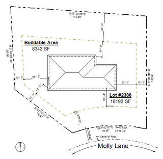
As a follow up to a related post last week this post describes how we can create a property line when we lack any digital data to use. The survey may be an old hand drawn document provided as part of the deed or it could just be a printed drawing that nobody can find the file for. While we wait for a new survey we can still start with what we have. We've captured some bearing and distance information from my old survey drawing.


When we have a CAD file we can import as a resource the Property Line tool option: Create by Sketching makes it pretty easy. Since that's not an option in this situation we need to choose the other option: Create by entering distances and bearing.


Take a moment to revise the project units so they show the same units as the survey data. It helps to confirm the values we see in the dialog match those we've entered (it's shown that way in the image, not in the video). When we enter values for bearing a space between Degrees, Minutes and Seconds is all that's needed. To advance from one field to another we can use the TAB key to move forward or SHIFT + TAB to move backward in the dialog.


Also note that if the distance and bearing information is accurate enough Revit will report "closed". If the data isn't then it won't be able to report "closed" or show the area of the property. Unlike many sketch based elements Revit will tolerate a Property Line boundary that does not close. I altered the distance for the last segment to show the following error message that appears.


Once the Property Line is completed, click OK and we'll find the element is "stuck" to our cursor expecting us to decide where to place it. We pick an arbitrary spot and then move it so a corner of the Property Line is at a corner of the building. The goal is to make it easy to use Rotate True North and define the angle between the current Project North position of the building and the side of the property we'd like it to line up with.

In this example we've decided that the side of the house needs to be parallel to the East property boundary segment. Now we can use Rotate True North. When the tool starts we need to choose where the Rotation origin should go. In this case we need it to be at the corner of the building, the same corner where the corner of the Property Line is now. The first pick is rotation origin, the second pick is on the building and third pick is on the property line segment.


The task is much easier when we put the Property Line right on top of the building as a frame of reference. It also allows us to define the angle without trying to determine what it actually is.


Now that the orientation is correct we can move the Property Line into the correct location/position. Adding dimensions makes it easier to be accurate. We need to double check the values to make sure the changes to one dimensional direction don't alter other dimensions inappropriately.


This is a video demonstration of the concepts with captions, no audio.


Friday, February 01, 2013

Lock Down Shared Coordinate Relationships

The more complicated a project is the more trouble someone casually (accidentally) moving a building file can create. The simplest solution is to pin a linked model to interfere with accidental movement. Moving a pinned link takes a deliberate action.

We can put another speed bump in the road by using Worksets as a security guard to make it harder to move a linked file. Assign each link to its own workset and then create a new username like "Link Admin" and while working as this user make each link's workset editable (take ownership of each link's workset). When you synchronize (SwC) don't relinquish those worksets. Next time someone accidentally drags a linked file they'll be warned that "Link Admin says no".

One more step you can take which also involves worksets is to make the Project Info workset editable too, for each building file. The Project Info workset is located in the Project Standards group.


Taking this approach prevents shared coordinates from being altered inadvertently or otherwise. Same strategy, same user, same refusal to relinquish the worksets this user borrowed. This needs to be done in all the linked models as well as a master site model if used to establish the shared coordinates.

Tuesday, May 01, 2012

Five Minutes with a Toposurface

I created a video to describe what happens when Revit contours don't quite match up with the underlying cad file contours that were used to generate a toposurface. The first part of the video explains that the Site Settings usually don't match the contour interval settings of the cad source file. Changing these settings is often enough.


When we want Revit to provide more contours than the source file provides it can but that's where we start getting some distortion of the contour lines we see. The rest of the video shows how to manipulate the contour lines with additional points to help Revit sort it all out.

Keep in mind that Revit creates triangles between points. You can see these if you use Visibility/Graphics to turn them on.


This is what the triangulation looks like before adding an extra point to help Revit draw the contour more accurately.


This is what the triangulation looks like after adding the extra point.

Here's the video embedded or watch it at OpEd Videos or You Tube instead.


Thursday, March 22, 2012

Property and Setback Boundaries

I wrote a couple posts before about documenting these. The first was about using the property line tool to create the setback lines too. I used Override Elements in View to make the line pattern different. The second was dealing with the notion of 3D representation of these boundaries. Have a look if you are seeking ideas for these site and property documentation issues.

Property Boundaries and Setbacks


Massing a Property Boundary

Friday, August 26, 2011

Location, Location and Location

The age old real estate advice this is not...

When you use separate site and building files to manage your project, it is possible to become confused between defining the Project Location (such as Wapakoneta, Ohio versus Amstelveen, Holland) and the Location related to Shared Coordinates. One is not the other. It is possible to also assume that setting the Project Location and then using Acquire Coordinates will pass along the location to the other project file (linked .rvt file). That is also not true, won't happen.

Project Location is unrelated to shared coordinates, at least as far as Revit is concerned. Location as defined in the Project Information dialog is used for solar/energy analysis (gbXML too), shadows and the like. Shared coordinates are used to align different files and information contained in potentially different file formats.

When "you" assign the location for a "site" file you are helping Revit understand that file's real world location but not the link. If you show shadows or render a view in the host file you'll get shadows based on that location, assuming the orientation of everything is correct (true north).

When you open the building file (linked) it understands the site coordinates for alignment purposes (accomplished through using acquire/publish coordinates) but it doesn't inherit the location setting because they are not truly connected together in Revit. The coordinates used do not necessarily define a "real world location" because of various methods (surveying requirements) that could be used to locate the building on site.

Short answer, assign the project location in both files or at least the building file if you want to show shadows and/or render there. Both if you want that option in both. The shared coordinate part is done once, from one or the other file.

Thursday, November 04, 2010

Dept. of Echo - Autodesk Office Gets Measured with PKNail

As a follow up to an earlier post Jim Foster (BIM and the Built Environment blog) recently did a site survey of the existing building using their prototype product PKNail.

The video at You Tube is just under 10 minutes long and demonstrates what they did in about three (3) hours of on-site time.


Friday, October 15, 2010

Dept. of Off Topic - Site Cleanup

I don't have a sense of how attached people are to what I've stored on this site but I do know that I've grown weary of scrolling my own site to get to various links. I've condensed all the links that I used to have on the right side bar to the maximum of ten sub-pages that blogger allows.


If you've become accustomed to finding something via my blog then most likely you'll find it on the sub-pages now. I hope that you'll find the shorter length of the blog page overall as pleasing as I do. Another advantage of the sub-pages is that I can use more html formatting to start considering flagging blogs or sites that I want to highlight as more active etc.

I have been told from time to time that people rely on the Builds and Updates page to check for the most recent build information. I try to keep that as current as possible and it is easier to check the build number here than on Autodesk's site since they buried the build number in the pdf they issue for each web update.

I also increased the maximum number of posts that can appear to five so that the posts and the sidebar are nearly the same length. I hope these subtle changes make the site a bit cleaner and clearer. As you were...

Thursday, May 06, 2010

Revit and FOUS

I wrote a post back on February 1st, 2010 about the Two-Mile-Limit imposed on importing CAD files. I referred to these files as FOUS or Files of Unusual Size paying homage to the movie, "The Princess Bride". It has been mentioned quite a bit already but I wanted to update my own blog to reflect the latest development with the release of 2011.


The limit is now 20 miles, though you can still import the file. A warning is generated but the file will still be permitted, unlike before. You can read the blog post at The Revit Clinic called, "Revit 2011 2 Mile Limit Now 20 Mile Limit".

Tuesday, August 25, 2009

Pads and Slope Arrows

I received a question the other day about an unwanted sliver of a toposurface element appearing. At first the assumption was related to Design Options because there was quite a bit going on. Turns out adjusting the pad and its Slope Arrow could resolve the issue. Here's a picture of Pad A and B. Pad "B" obviously has the sliver problem.


Pad A is two pads, one flat and one sloping. Both pads are set at their lowest elevation and the Slope Arrow tells the pad to go UP. Here are the properties of the sloping pad.


And here are the properties of the Slope Arrow for A.


Pad B is also two pads but they are defined a little differently.


Pad B's Slope Arrow properties.


When you need a pad to slope it seems that it is more reliable to define the lowest elevation and work up than in the reverse. At least it helped resolve this sliver.

Wednesday, July 22, 2009

3rd Party Applications - Eagle Point and Tools4Revit

There are a growing number of companies creating specific products intended to expand or enhance working with Revit.

Building Framing and other Utilities:
Recently Tools4Revit made their work available to me and I've been slowly working through their pretty comprehensive set of tools. I plan to post about some of their tools as soon as I feel competent to do so.

Site and Land Development:
I hope to get a chance to see the latest development from Eagle Point Software called LANDCADD for Revit. LANDCADD is hardly new but support for Revit is brand new, new enough that there isn't much information on their site yet. The release is tentatively scheduled for October 2009. You can read their press release HERE.

Tuesday, September 09, 2008

Using Revit is Safer than This!

These two images were acquired from this site. These guys are lucky to be alive, assuming they still are!


The old "level the scaffolding with whatever you find lying around trick"!


Thanks to this site for the image.

Friday, July 25, 2008

Revit Curiosity - Revit Civil

A frequent request among Revit users is more site tools. In fact it was the number one AUGI Revit Wishlist item last year, which was submitted to Jay Bhatt (Senior Vice President, Architecture, Engineering and Construction Solutions) at Autodesk University 2007 during the AUGI Annual General Meeting.

The site tools we do have work pretty well at their given task. This begs for the next level. Simple equation, with each improvement in work flow a new greater expectation is created because, "This works so easily...why doesn't it do xxx too?"

So I wonder what we mean by more site tools?

I believe that we want tools that allow us to prepare and "finish" planning exercises as well as fully articulate our design for both documentation and presentation purposes. I don't believe that we (architecture)(okay maybe some do) want tools for hydrology or that we truly intend to compete with the technical expertise of our civil design consultants. We ARE looking for a way to "democratize" the design of these elements so that we can better inform our discussions with our consultants.

I'd like these (at least):

Define road profiles and then describe where they will go relative to our project and at what elevations they will do so.
Curb/kerb tools to describe how these relate to the design of our roads.
Drain representation that alters the site or road/curbs.
Retaining walls and site topography alteration accordingly.
Contour definition by more means than points, such as sketching lines.
Bi-Directional relationship between civil data file and toposurface (if civil data is updated the surface updates)
Solid vs. Surface Topography to support subterranean work such as tunnels.

Ideally the effort applied to drafting such items in a conventional 2D drawing would create a 3D version of same. Autodesk would like us to consider the Civil 3D product as the tool for this work. For a Civil design firm perhaps it is. I respectfully submit that it might be similar to using a scientific calculator to figure your grocery bill. A bit more power than I need.

If we accept or agree that architects usually start projects and the other trades get involved later (hopefully this will change too) then we must recognize that it is therefore necessary for architects to make many decisions (to express ideas) early on and document those decisions/ideas effectively.

Site tools are an important part of this process and for Revit to exclude them diminishes its effectiveness as a complete solution. Revit needs to provide tools to allow architects to get their designs approved in as efficient manner as possible. Adding site tools to the Revit toolbox would be big help!

P.S. We could include parking lot design tools and landscape design in this equation as well. There is existing content (not comprehensive though) for these tasks but it can be argued that there is not a discipline oriented process for them however. We'd be much better off if there was.

Wednesday, January 10, 2007

Revit User's Residential Example Project - Diary

Robert A. van het Hof, Assoc. AIA created this SITE as an example for a computer user group that was discussing 3D modelling software. Let him know what you think. He says on the site that it is a temporary web site so I don't know how long it will exist, check it out! Here's one of the images he posted: