Showing posts with label Walls. Show all posts

Monday, June 17, 2024

Short Curved Walls and Non Core Layers

At Autodesk Revit forums I saw a post regarding disappearing curved walls. These walls were shorter than the current view range cut plane. When the Wall subcategory Non Core Layers is turned off only these curved short walls disappeared. Other walls of the same type that were straight remained visible. It looks like a bug to me.

In my testing, when the sub-category for Non Core Layers (Detail Level must be Medium or Fine) is turned off the wall will disappear when it's height is not at least 2 feet above the cut plane setting. For example, I can make a wall disappear if it's height is less than 6 feet when the cut plane (view range) is 4 feet. Enter anything 6 feet or higher and the wall reappears. This image is some full height walls and some walls that are 4 feet tall (lighter gray walls).

This is the setting I turned off in Visibility/Graphics.

This is the result, the curved 4 foot tall walls are gone.

I suppose, in their defense, they could argue that the reason it is possible to turn off non core layers is to be able to isolate, only show, the structural portion of walls. As such a curved wall that is not tall enough to reach the cut plane is not likely to also be a structural/bearing wall. At the very least it is unexpected to have a wall disappear only because it is too short and curved.

Cue Randy Newman, "Short walls got no reason..."

Thursday, July 20, 2023

Slanted Walls Don't Miter

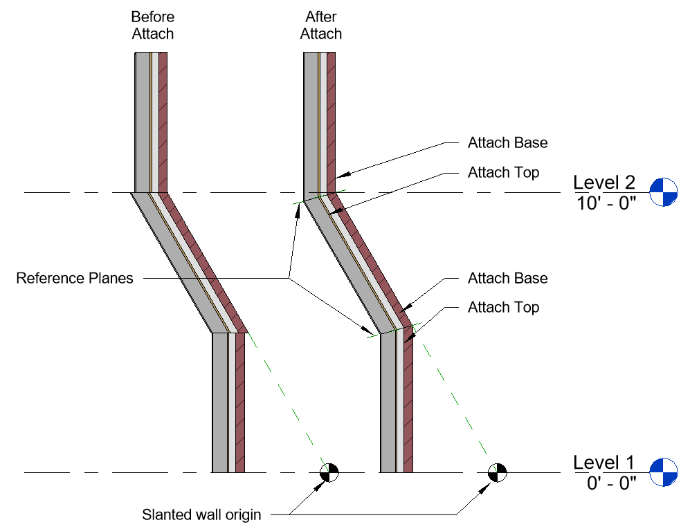
What if I'm asked to create a vertical bottom wall that will transition into a slanted upper wall? Initially the wall configuration looks like the walls on the left in the following image. I added another vertical wall at the top of the slanted portion just for fun.


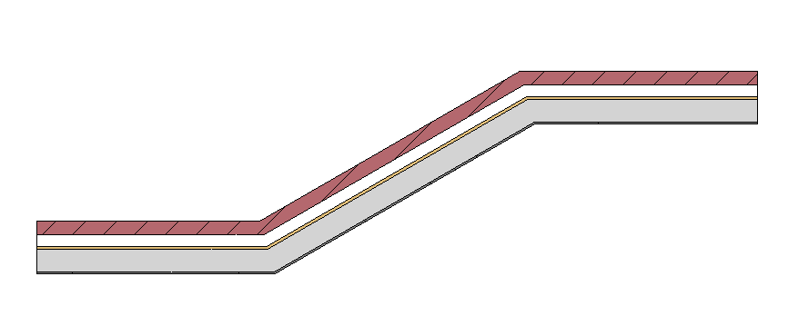
Each wall doesn't know anything about the other so there is no attempt by Revit to miter them together. We might have expected them to join? If we consider what happens in plan views for a similar layout (see image) I don't think it's unreasonable to think that might have happened. If an automatic join occurs in plan views maybe using Join will work in a section? No. Wall Join tool? No. Attach? YES!


To resolve the clumsy look of the left walls and end up with those on the right side of the image we can take advantage of the Attach tool. We just need to add reference planes to define where the miter joint should occur. Then Attach - Top will fix the bottom wall and Attach - Base will fix the upper wall. Repeat as required until all walls relate to each other better.


Tuesday, June 18, 2019

Eccentricity of Wall Footing

I replied to a thread at AUGI regarding the Eccentricity parameter of a Wall Footing. They observed that Revit seemed to ignore their input and didn't understand what it was meant to do. In this case the width of the footing was less than the value they entered.

The parameter is intended to shift the footing over, from interior to the exterior face of the wall. The footing starts out centered on the wall above.

The maximum eccentricity is equal to (Footing Width/2)-(Wall Thickness/2).

The interior wall surface can be aligned (flush) with the interior face of the footing but not further, creating any overhang of the wall, which seems logical to me. A picture might help?

Thursday, May 23, 2019

Structural Column Disappears - Part Deux

Yesterday while trading messages with a friend we discussed my previous post about columns disappearing. He suspected it might explain the issue he was observing. After looking more closely it turned out that it doesn't. In his situation the structural columns were modeled the full height of the building and Join Geometry was used on walls, that passed through (overlapped) the columns, at each floor (level). The result: at some levels no column appeared while at others they do.

It was necessary to pull the walls back so they stop at the surface of the columns. Join Geometry allowed for the desired appearance and the columns reappeared at the other levels where they were missing earlier.

Tuesday, February 20, 2018

Copy Monitor - A Different Way?

Morning musing...

It's my observation that there is a prevailing mostly ambivalent attitude toward the Copy/Monitor (C/M) features. I've said before that I think the order of the tabs in the Options dialog are based on the likelihood that we'll use them. Specifically they are listed left to right: Levels, Grids, Columns, Walls and Floors.

C/M isn't hard to use but once it is in play we've got some new rules and warnings to contend with. The process depends on us identifying the elements we want to live in the C/M system. I understand the logic of that choice. Revit asks us to tell it what is important enough to us to engage the system.

Perhaps we need a completely different way to attack the problem? One that doesn't require the advance work. One that is more a reaction to work as it is created and shared, that merely exists.

I wonder if it would be more betterer if we could run a Level or Grid check as a process. The application would compare elements and compile a report, observations and differences. It could be something we read afterward or presented in a dialog for immediate action.

For example, it could just start with: "Hey Steve, there are 27 grids in your model and 30 in theirs. You should look at them." Take it slightly deeper, "Hey Steve, there are three grids that share the same name but are not in the same location."

Does it matter that they used to be in the same location and they aren't now? The application would have to start storing records for past results to do that but it could be useful to determine when or how things got off track. The rules or conditions that are interesting need to be defined.

This sort of element review and comparison doesn't have to be limited to the five that Copy/Monitor were designed for originally (overlooking the MEP elements that have been added in some fashion). It still requires two or more elements though; mine, yours and theirs. The redundancy is annoying but it does provide us with flexibility within our own models.

I imagine much of what I'm describing (and more) is possible via the API and Dynamo. It just needs someone to decide it is an interesting enough thing to do.

Thursday, August 13, 2015

Revit 2016 - Copy Monitor - Wall Location Line

I don't recall any mention of this appearing in the What's New documentation or presentations. I stumbled into it the other day and meant to write about it but my aging Dell finally bit the dust and that distracted me. I find this new parameter and options appears when I examine the Walls tab in the Copy/Monitor Options dialog.


Interesting isn't it? I experimented with using the option. This image depicts a linked file with compound architectural walls being used to create Stud Only walls in a structural model.


I specified that C/M should create a Stud Only wall type instead of the compound wall type being used by the architectural model. I then used the Location Line: Core Face:Exterior.


I didn't find any help documentation to support this new feature. What I did find declares that C/M just uses the Wall Centerline for alignment, which was true until now!

Also, fwiw the openings created at the doors and windows are the correct sizes but only because the families don't have any additional geometry beyond the extent of their frames. I placed openings in the walls at the curtain walls manually using the Wall Opening tool (Architecture or Structure tab > Opening panel > Wall).

Wednesday, April 29, 2015

Revit 2016 - Edit Multiple Wall Joins

We can select more than one wall join intersection and Allow or Disallow Join. Start the Wall Join tool, press the CTRL key and select each intersection that you want to alter. Then choose the join condition you want.

We can use a window selection and we can also use the TAB key to select several wall intersections at once, according to varying circumstances. If there are no intersections that have already had Disallow Join applied then you can potentially select all the intersections in the same manner as we can select a chain of walls with the TAB key.

It is a bit fussy when using the Allow Join option after using Disallow Join. The walls don’t heal automatically. Initially it seems that using Allow Join only changes one of the two walls at each intersection back to allow a join to occur. The icon for Join appears for one half of the intersection each time. We might infer from this that it is necessary to select a grip and drag or at least wiggle the connection a bit to get them to join back together well.

It is important to realize that there are two walls at each intersection and it is necessary to select them both! If we are careful to select them both then the walls will heal up nicely.


Here's a short video (1 min) to demonstrate it.


Tuesday, December 24, 2013

Wall Openings and Room Area

Fwiw, I wrote these related posts: this one in 2005 and this one in 2006. This is ONE Too, it's about creating openings when we use Copy/Monitor (it's still not a good idea unfortunately).

A recent thread at RFO started off by asking which method is best to create openings in walls. There are a few options: Family (like a door, window or generic model opening family), Wall Opening, Wall > Edit Profile, Automatically Embed feature of Curtain Walls or even an in-place wall with a void.

Like anything understanding their differences is important. For example if I need a round hole in a wall I could use a jigsaw, sawzall, Xacto knife, sledgehammer, hole saw, drill bit etc (or dynamite). Depending on the size of the hole I need any of those could provide a hole with varying degrees of accuracy, success and effort.

Revit's Wall Openings, apart from being a bit weird to use, affect room bounding differently than other techniques that cut a wall. In the attached image:
  • Left side of Image: a Wall Opening doesn't respect (alters/affects) the bounding nature of the dividing wall and using Edit Profile affects room bounding of the wall too
  • Center of Image: a opening family does respect the wall's room bounding
  • Right side of Image: A wall opening allows area to extend "into" a host wall where a curtain wall needs to go while a curtain wall (top wall) that uses Automatically Embed (bottom wall) instead does not
  • Added image (right image) shows same conditions but with using Edit Profile on the wall in the left side of the image


Here's what the model looks like in 3D, the view range cut plane for the plan view above is the typical 4'-0" (1200mm ish). If the wall opening comes into contact with the Computation Height of the host level it "affects" the room bounding. Added a wall opening (like a window) to the middle building.


By the way for trivia fans, Jeff Hanson (Autodesk SME, User Experience) wrote: "... the wall opening tool was created specifically for creating a wall opening in a wall that is curved in plan. There is no way to edit the profile of a wall curved in plan..."

Added this image in response to a comment from Rob (1/3/2017). I used Edit Profile and Wall Opening to create the openings and then placed Room Separators to decide which room should get the area between them.

Wednesday, October 23, 2013

Tagging Elements and their Area

Revit allows us to tag rooms and spaces to display their area. If I'm tempted to do the same for Walls, Floors, Ceilings or Roofs the list of available system parameters (built into Revit) does not offer Area. Revit MEP users can tag a Duct's area.

It seems to me a bit arbitrary to disallow the tagging of data that is part of the element. We can see it in the element properties and include it in schedules. While a schedule is an ideal way to summarize data a floor plan is useful to provide context AND display a variety of information, like area.

It would be excellent to see more parameters unshackled.

Friday, October 11, 2013

Room Separation Line Overlapping a Wall Error

Another inspired by email: When you sketch a room separation line and it overlaps a wall you'll get yelled at. Revit will also store the warning for you to deal with later using Review Warnings if you don't resolve it right now, when the warning first appears.


If you change the Wall's Room Bounding property so that it is "off" or un-checked you'll still get yelled at when they overlap. Revit isn't checking to see if a wall is room bounding when it catches the condition. It's only concerned that they both overlap. No grace for you!

Monday, June 11, 2012

Detail Level Ignored with Unlocked Wall Layers

We can unlock a layer or layers in a wall to allow "pulling" them up or down separately from the rest of a wall. This makes it possible to create a brick veneer that drops below a level some distance or pull the stud layer up farther, like this.


To make this possible you need to edit the wall's structure and select a layer to unlock, like this: 1 - Click Modify, 2 - Select the edge of a layer, 3 - Unlock the padlock

Interestingly, in Ceiling Plan views only, when we take advantage of this we lose the ability to show just two lines with Detail Level: Coarse.

I suppose it makes sense somewhat, since they are now distinctly separate but the hope was that we could still see just two line in Coarse. Seems to work fine in plan views though.

Wednesday, April 11, 2012

Wall Floor Interaction and Linked Models

When we have architecture and structure in separate Revit models we end up with somewhat clumsy graphics in wall sections. This is more pronounced if the structural slab is in the structure model only. It could look like this.


The wall continues past the floor as if it isn't there. One possible solution that allows us to keep the structural slab in the separate file and avoids the copy/monitor scenario is to place a Reveal on the interior side of the wall. The profile needs to be equivalent in size to the slab thickness and the wall thickness (inside surface plus however far the slab extends toward the exterior). This approach creates a bit better result.


I should mention that this works the other direction too, since the reveal is part of the wall it will leave a "hollow" space for the structural model's floor slab to occupy.

Tuesday, February 07, 2012

Short Walls don't Look Right

This is re-post or echo of a post I wrote six months ago. The subject came up again in a couple emails.

I was positive I wrote about this in the past but I can't find a post in the pile of posts I've made since the end of 2004. I suppose it could be buried in a post at AUGI...

If a wall is less than six feet (or 2000mm, no not exactly equal to six feet) it will NOT use the Cut line weight, it will only show using the Projection line weight. You can "force" Revit to show it as Cut by setting the Top Constraint to the level above and using a negative Top Offset value to drop it back down to it's intended overall height. A bit obtuse but it works! [Added this: Chris mentioned in a comment, "you can set the Top Constraint to the same level as the Base Constraint and then use a positive value for your Top Offset value."]


I thought to post this (was thinking re-post but couldn't find a first) because it came up during a session at RTC (during Harlan Brumm's Troubleshooting class) and then was tweeted.

It is also documented in the current WikiHelp.


Keep in mind that if the height of the low wall is still lower than the cut plane of the view's view range setting it will not show using the cut lineweight, only the projection lineweight. The distinction of this post is for walls that are taller than the cut plane but not quite tall enough (six feet).

You can read the series of comments in my earlier post regarding Low Walls.

Monday, February 06, 2012

The Fat Pen - A Tale Two Lines

Every now and then I read or hear someone say that it is faster (in early design) to just sketch lines to create a quick floor plan for concept design (often as a justification for doing the work outside of Revit as well). I also hear that if we are going to do that (in Revit), we should just use Room Separation lines because we can put rooms in to identify them. I think both notions are "off", use walls.
    "But Steve I don't want two lines, I just want a "fat pen" (think Sharpie)."
I say either sketch using really thin walls or use the Coarse Scale Fill Pattern as intended. That's my choice because they aren't any more work than sketching lines (ignoring their height), they provide boundaries for rooms and they can host doors and windows. It's also simple to change them to a better type later. If you use room separation lines first and then need walls you have to recreate stuff that's already there, they just aren't the right "stuff".

Years ago I worked with a guy that I found sketching lines in plan first. I asked why and he said he needed the lines to know where to put the walls. Somewhere deep inside we have this notion "we must draw lines". Everything he was doing was just as easy to do with walls instead...he "needed" lines first. Sometimes we must forget what we know. ~ Try walls, you'll like'em.

Still thinking that those "lines" are better than walls? Can those lines do this? (Please don't be distracted by my clever building design)


Okay, sure they can do that but what adding rooms and doors?


And then a few clicks more...this?


or easily changing to look like this instead (by changing wall types to use "Coarse Scale Fill Pattern")?


Can those lines generate cool shadows? (well, I think they are cool)


or switch to a more construction oriented appearance by changing "Detail Level" (okay, should have turned off the shadows)?


Do I really need to bring up schedules or 3D views or sections/elevations or enlarged views or ceiling plans and so on? I guess I just did. Walls set the stage for everything else downstream ~ I say use'em!

Wednesday, August 03, 2011

Wall Creator by Clark Dietrich

Steve Bennett shared his insight about a new Revit wall tool he's been beta testing recently.


ClarkDietrich publicly asked for some beta testing assistance this past May. I haven't used it myself but Steve seems pretty pleased with what he's experienced using it. Check it out!

Here's a You Tube video from their site:


Monday, June 27, 2011

Low Walls

I was positive I wrote about this in the past but I can't find a post in the pile of posts I've made since the end of 2004. I suppose it could be buried in a post at AUGI...

If a wall is less than six feet (or 2000mm, no not exactly equal to six feet) it will NOT use the Cut line weight, it will only show using the Projection line weight. You can "force" Revit to show it as Cut by setting the Top Constraint to the level above and using a negative Top Offset value to drop it back down to it's intended overall height. A bit obtuse but it works! [Added this: Chris mentioned in a comment, "you can set the Top Constraint to the same level as the Base Constraint and then use a positive value for your Top Offset value."]


I posted this because it came up in a session at RTC (during Harlan Brumm's Troubleshooting class) and then was tweeted.

Wednesday, February 10, 2010

Walls and Footings

Darryl over at CADCLIPs posted a video overview of creating stepped footings using an in-place family. I recently had this conversation with a client and showed him the same process but also showed him another technique that is worth doing.


So Darryl did one, this is the other brother Darryl. This method uses a floor as the "footing", a floor slab edge and profile. Wrapping it up is attaching the base of the wall to the "floors". I posted the VIDEO here.


Friday, August 21, 2009

Hotfix Revit 2010 Platform - Walls

The Autodesk Update site has a new Hotfix item. The description is a bit vague: This hotfix addresses issues related to deleting or modifying walls, a crash may occur.

You need to make sure that you read the Readme file. You need Web Update #1 installed first too. There is a hotfix for 32 bit and 64 bit versions. Surprisingly low tech patch process. Same hotfix applies to each version so just repeat for the others if you have them too.

It's a good idea to keep an eye on this site every now and then.

[Edit: Aaron Rumple posted at AUGI that this hotfix disables the 2009 UI Revit.ini hack that permits users to use the 2009 user interface instead of the Ribbon. Stay tuned to the thread or here for an update.]

Saturday, June 27, 2009

Compound Walls - How Much?

While attending a Revit user group meeting a month or two ago someone mentioned that they prefer to use generic walls to keep their model size (file size) down. It seems reasonable that a compound wall might carry a bit heavier burden on a model but how much more of a burden? The poor scientist that I am I tried the following.
I saved an "empty" template file with no walls placed which resulted in a file of 2076 kb (used Default.rte, the stock Revit template). I then created 19 walls, 4 exterior and 15 interior walls using Generic 12" and 6" respectively. When I saved this file it was 2216 kb. Then I created another but used compound walls (Exterior - Brick and CMU on Mtl. Stud and Interior 5-1/2" Partition(1 hr)) instead with a resulting file size of 2452 kb for an increase or difference of 236 kb. I used the exterior wall type because it is more than just a wall with extra layers, it has embedded sweeps and reveals which should account for some of the difference as well.

A small number of walls. I thought I'd use more this time. I created another pile of walls for a total of 152. This is the result.

The generic walls file came in at 3184 kb and the compound version came in at 4092 for a difference of 908 kb. Here's a spreadsheet breakdown for you "column and row" types.

It seems to me that this means that modelling walls in bulk results in less cost (in kilobytes) per wall. The more walls the more economical their impact is. Not that more walls doesn't mean more...just not a literal 1:1 file size relationship. It also means that compound walls do have a "heavier" impact on the project file size too.

Since I increased the number of walls by eight (8) times I was curious to see if the kilobyte increase was literally eight (8) times as well. The How Close? column in the spreadsheet shows that the generic walls were nearly so but the compound walls were a bit more economical when the quantity increased, just a little over five (5) times as many kilobytes.

To make it more interesting we could edit the profile of walls, attach walls to roofs, embed curtain walls, disallow joins, add views to sheets using different Detail Level settings, place various hosted elements on/in walls, use the Opening Tools, compare curved versus straight impact...and on and on.

Do I have a point? Well...file size isn't really the only measure of a project's performance nor is it even really reliable to use to predict project performance. I've seen rather large projects that perform quite well apart from waiting for it to open initially. Conversely I've seen "small" projects that perform poorly. My interpretation of my results is that I shouldn't really need to worry about using generic walls only, at least not using just file size as a measure. Much more likely that how the walls interact with other elements in the project will affect performance more than just file size.

Thursday, January 01, 2009

Moving or Dragging Multiple "Ends"

I received a question this morning asking if it is possible to select and change the position of ends of more than one wall by dragging them at the same time. When I read this I imagined that the walls are parallel but they don't have to be.

The answer is, sure, hover over the end of a wall and use the TAB key to highlight the "shape handle" of the wall. This end line/edge of a wall is called its Shape Handle. Repeat that process and by using the CTRL key you can add the other shape handles to your selection till you are done.


Then either drag them or use the move tool. Dragging is not precise unless there is something you precisely you can drag "to". Move can be more precise because you can specify a distance.


Then again the Trim/Extend tool might take less effort?