Showing posts with label Graphics. Show all posts

Monday, December 30, 2019

UnHelpful Help Location URL

I read about quirky Reviteristic issue at RFO this afternoon. A weird graphics glitch occurs when we interact with the Help Icon families that use the URL parameter feature to reference an external document. This is an example of it in the sample architecture model that ships with Revit (rac_basic_sample_project.rvt - in imperial content).


When we select the icon and examine its properties we get this Learning Link parameter.


When we click in the field the small button appears with the ellipsis icon. Clicking on the that button will take us to the URL saved in family.


The trouble begins after we move our cursor away from the field and start to resume work. The URL is stuck on screen over another parameter like below, the Detail Number parameter for the view.


I noticed that I can work past the issue if I click in the Default Analysis Display Style field, which I presume works because it also has an navigation/ellipsis style button.


I also noticed that if I am careful to click on the field right above the Learning Link, called Location, before leaving the Properties Palette I can avoid the issue too.


The forum thread was talking about this in 2019 but these images are from 2020.2. 

Thursday, November 28, 2019

Revit 2020.2 Internal Origin Redux

Happy Thanksgiving to those who observe!

One little thing I'm thankful for, I got a file yesterday from Autodesk (TurnOffInternalOrigin.Dyn) that is meant to be run in Dynamo Player (it's a custom node in testing ATM). You can download the file, place it wherever your Dynamo Player is looking for files already or in Dynamo Player just browse to wherever you placed the file. Click the play button (see image) and it will turn off the Internal Origin in all views. This approach means very little Dynamo knowledge is necessary, just enough to get Dynamo Player open and find the file.


Since I already put in some time with my own graph which included the Survey Point and Project Base Point I decided I'd like to be able to turn on/off all three or just the internal origin or some combination. I modified my graph (Control Coordinate Graphics.dyn) to provide input options (see image).


When you use Dynamo player you can edit the input options through On/Off switches (see image).


Click the little Properties button (looks like a old Macintosh computer to me). Clicking the toggle will make the statement either true or false for each "hide" question. All three true = all off for example. Remember my graph is dependent on a node from the Archilib package, make sure you've installed that before trying to use it.

Thursday, May 23, 2019

Structural Column Disappears - Part Deux

Yesterday while trading messages with a friend we discussed my previous post about columns disappearing. He suspected it might explain the issue he was observing. After looking more closely it turned out that it doesn't. In his situation the structural columns were modeled the full height of the building and Join Geometry was used on walls, that passed through (overlapped) the columns, at each floor (level). The result: at some levels no column appeared while at others they do.

It was necessary to pull the walls back so they stop at the surface of the columns. Join Geometry allowed for the desired appearance and the columns reappeared at the other levels where they were missing earlier.

Monday, May 20, 2019

Structural Column Disappears in Detail View Type

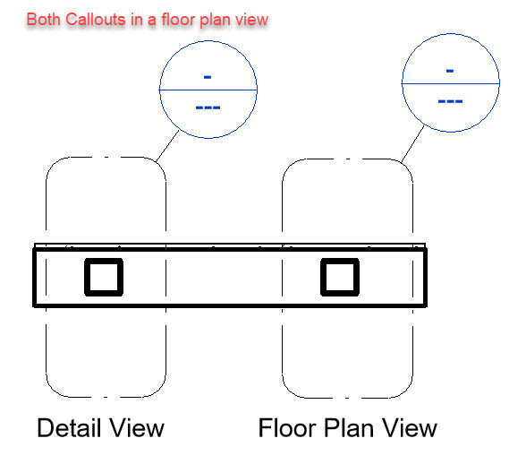
When we create a Callout within a plan view we can choose between Floor plan and Detail. A structural column that uses a negative offset won't show up when a wall exists in the same location when a Detail view type is used. It works fine in a Floor plan view type.

Here are some example images. The first one is showing the negative offset used. If the offset is zero then there is no graphical issue, the column shows up.


This image shows both callouts in the overall floor plan, Detail on the left and Floor on the right.


This is the Floor Plan Callout, column shows up as expected.


This is the Detail Callout, no column is visible.


This is the same Detail Callout but my cursor is hovering over the column and Revit sees it, highlights it despite not being visible. The wall is masking the column.


This is the same Detail Callout but the view is changed to use Wireframe and the column appears.


It boils down to the negative offset applied to the column. The graphics hierarchy does not respect the full height of the column and the wall element is drawn over the structural column. We can also get around the issue if we edit the column family and remove the option: Show family pre-cut in plan views.

Tuesday, August 21, 2018

Section Line Annotation Alignment

No, not the 2019.1 feature that allows us to use the Align tool on sections...

If you find yourself wondering why you don't the get the telltale dashed lines to help you line up section heads or tails check Visibility/Graphics for the view and make sure Lines are checked (visible). If the category is turned off, so too are they. These...


Check this...

Friday, October 28, 2016

Structural Plan View - Column Symbolic Offset

From the Dept. of Subtle we only find this parameter in Structural Plan views.


The help documentation says we can use this to "Specify the offset of a beam join to a slanted structural column. This only applies to coarse detail levels.". I've mocked up some framing to see what it does.


In this next image I've changed the offset value to 5'-0". You'll notice that the column symbol moved down toward the bottom of the column.


In this next image I've changed the offset value to -5'-0". You'll notice that the column symbol moved up toward the top of the column.


If a column doesn't pass beyond the view's level a negative value doesn't do anything to change that column's symbol location. Pretty subtle...

Friday, September 30, 2016

Imported or Linked DWG Appearance as Generic Model Broken in 2017

Using Revit 2017, I have a 3D DWG file for some framing that I want to use as a coordination reference within a project file. Initially I linked the file directly to the project but that approach (unfortunately) doesn't respect the cut plane of a plan view which, for example, means cripples above a header show up in the plan view too (header as well).

I decided I'd use the old create an in-place Generic Model family trick.

If you're with me so far you're probably expecting what I expected; to find that Revit regards this imported 3D geometry as generic model (cuttable) category information, giving me the look I wanted. However, when I clicked Finish Model the linked file disappeared entirely.

I thought for a moment, "Am I just imagining that I could do that? I swear Revit used to do this?!?"

Hmm, I decided I'd create a component Generic Model family instead and use Import CAD. This way I could replace the source CAD file if necessary.and just reload the family later...if necessary. Also thinking, "...maybe it'll work this time, this way...?" Nope...

I gave in, I did a quick search using Revit Help and noticed a result called "Regression Revit 2017 - Cutting 3D DWG with section results in inconsistent model display".

NUTS! ...at least I'm not crazy (about this at least)...

Well I'm writing to declare that it's not just an issue in section views. The damn thing doesn't show up in a plan view at ALL.

It works as I remembered in Revit 2016...project is in 2017 though.

I did try creating the family in 2016 and let Revit upgrade it in the 2017 project...no joy...busted. I also created a Specialty Equipment family (in-place too) and it shows up in plan view but since that category doesn't cut...it's missing the point, my reason for traveling this road in the first place.

sigh ... next service pack, update release, patch...(whatever they're going to call...)

Wednesday, April 27, 2016

Multi-Segment Grid and Crop Boundary Interaction

When one segment of a multi-segment grid passes entirely beyond a views crop boundary that segment is not displayed. That seems reasonable to me. The annotation at the end of the grid however also disappears and that doesn't seem as reasonable to me. I'd like that to remain especially since (when) that end isn't coming into contact with the crop boundary. It is easier to see with a video capture embedded below. Whaddyathink?


Friday, April 08, 2016

Smaller Grid Bubbles

I wrote about one way to achieve using smaller grid bubbles in different views HERE. That written I can't help but wonder how much smaller is appropriate. A user recently complained they need a smaller grid bubble in a 1:1000 (metric) view. My gut reaction was "really?...maybe the grid bubble is just too big to begin with?" For example, this is what 1:100 and 1:1000 scale views look like side by side for a tiny footprint of grids using a stock grid family (6.5 mm radius/4.5 mm text).


That image is captured after using Zoom to Fit. How effective are grid bubbles at that scale to begin with? In imperial units that's equivalent to a view scale of 1"=120'-0". Keeping in mind that Revit's bias is to maintain the printed size of annotation, how much smaller does the bubble and text need to be to be better but still useful? This next image is the same sheet with grids bubbles that are half as big, text half as high (3.25 mm radius circle and 2.25 mm text).


I could argue that if the 1:1000 scale size is acceptable it might as well be the standard for all the views? This is how it (the smaller size grid bubbles) looks if I use Zoom Sheet Size and pan the view to show the grids side by side. This is more representative of what it will look like on the printed page.


Having the ability to turn off the bubble graphics only leaving the Grid name's text only might be a nice option. It seems to me that decreasing the size of the text means it is likely to no longer be legible. That's never good for documentation. For example, quite a few standards dictate a minimum text size of 1/8" which is larger than the 2.25 mm text I've shown in the images above.

Using a smaller font than what is shown above is going to start being too small to read on half-size prints; which is what I see getting printed more often these days. Fwiw, it's my understanding that 1/8" text as a requirement was decided upon because half size documents are printed so often and the resulting 1/16" text is at the brink of no longer being legible so standards set it accordingly.

Regardless, it's a frequent enough request that the development team ought to see what they can come up with. Something that is easy to implement and provides more flexibility for documentation.

Friday, March 04, 2016

Worksharing Display - Owners

The first thing I do when a project is open, to get a sense of things going on around me in the model, is to toggle on Worksharing Display - Owners (see image). That gives me a quick snapshot of who else is working on things around me.


If I see a color on anything I thought I'd start working on then there is no point attempting to edit those, I'll just get a warning from Revit in response. The mere presence of colors indicate other people are around, in this context. Hovering over one element brings up a larger tool tip than the usual information we get, including which person is currently editing it.

I use the Worksets option for Worksharing Display just to see if things are obviously assigned incorrectly. Again, hovering over any element tells me what workset it is assigned to in either the normal tool tip (first thing displayed, unless Design Options are involved too) or the expanded one for Worksharing Display.

I think most people forget about or overlook the Gray inactive worksets option too. That helps me cope with my nemesis Active Workset because it reminds me which workset is active because the things around me are either bold or not (see image).


Prompted by a reply to a thread at RFO.

Sunday, February 21, 2016

Clearance Subcategory in Linked Files and Families

You've linked a model that has families which include clearance elements. That's excellent for doing clash detection. However you may not really want to see the graphics they've provided for this in all of your own documentation views.

Hopefully the clearance elements have been assigned to a unique subcategory that you can control by overriding the link's Visibility/Graphics.


If so and you'd like to control the subcategory without overriding their linked file you can use Copy to Clipboard on one of the families (TAB to select it) with the clearance elements in them. Then paste a copy somewhere in your model. Now the family's subcategories are part of your own model. You'll be able to control it via V/G without overriding the link, assuming the link is assigned to By Host.


You probably realized that doing the above is a shortcut to creating a matching subcategory assigned to the correct category in Object Styles ourselves. It is a shortcut because we probably won't know what subcategory the family is using without examining the family more closely, by opening the linked file and editing the family directly. Using Copy and then Paste provides us with a copy we can interact with directly instead and any subcategories it has are brought into our project for us.

Families are prone to inconsistency because they can be obtained from a variety of sources. Consider that even the families from Autodesk aren't entirely consistent from one to another. It may still be necessary to crack open a family to find out how their clearance elements are controlled. For example, the lines that form the "X", and the "box" around them, in this family are assigned to the Hidden Lines subcategory, not Clearance.


In 3D there are forms to indicate clearance requirements and they are assigned to a Clearance subcategory but they also have their Visible parameter unchecked which means we can't see them in the project at all, anywhere.


This family does not intend for us to turn off the clearance "X", at least not via its Clearance subcategory. It has a subcategory called clearance and the solid forms for its clearance zones are assigned it but then it was decided they shouldn't be visible at all. By the way, doing so does not prevent Revit from seeing the clearance forms when using its own Interference Checking. However in Navisworks they don't show up. That might be considered bad form (pun intended). From a family editor perspective (and user), it would have been more flexible if the Visible parameter had been associated with a Yes/No parameter to allow us to turn it on or off if necessary. Unfortunately, keeping in mind that this post began about families in a linked file, it wouldn't make any difference for us.

Consistency is easier to manage and achieve when it is your own content library and your project files. It can be a bit trickier dealing with the content that is part of the linked files you need from other disciplines. It's easy to create a family that makes me happy, or my team. It may not make the other consultants happy though. Something to think about while you're being happy making content.

Wednesday, January 13, 2016

Pre-Selection and Selection Color

I always change the default color that Revit uses for selected elements. I use Red.


The default setting is the same blue that is assigned to Pre-selection. I don't recall when that changed but somewhere in the fog of time it used to be assigned to red. I happen to like the visual confirmation, the difference between what is highlighted and what is selected. To each their own.

If you want to change it too: Application menu (Big R) > Options > Graphics page

Friday, January 08, 2016

Text Box Boundary Quirk

I read a thread at AUGI describing an issue where the Show Border option to create a box surrounding text fails to completely surround the text it contains. First, if you weren't aware of it, each Text type has a type parameter called Show Border.


The Show Border feature worked fine until I used the Underline override to put a line under the NOTES: heading. It also happens if I use any of the other overrides; Bold or Italic.

I created the following video to show what happened.


Seems easy enough to resolve, just use separate text for the heading. Unfortunately I found that Show Border fails to work properly if the text is altered later too. Just adding a new line to the text is enough to confuse the border/box. Sadly this means the concept of Show Border is fatally flawed...

Wednesday, November 18, 2015

Walking and Relative to View

When we turn on shadows in a camera view they are affected by a subtle setting called Relative to View.


This setting is part of the Sun Settings dialog. When we turn on shadows in the view, activate the Steering Wheel and use the Walk feature the shadows will move as we walk when Relative to View is checked.


This caught me off guard today while discussing it (the Walk feature). One of the guys noticed the shadows were moving and remarked, "Why are the shadows moving? That can't happen as you walk through a building or around it!"

I wasn't focused on it, didn't even notice it... It took me a moment to get out of my fog, and in that moment, I even imagined Walk was moving the building instead of the camera (walking to and from the building). Then I opened the Sun Settings dialog to check things and another person said, "Oh it's got to be that!" (Relative to View). Yep...

When the option is not checked the shadows stay fixed relative to where the Sun is located. Crisis averted :)

Wednesday, September 02, 2015

Transparent Elevations and Large Coordinates

Back in December 2011 The Revit Clinic shared a post called Interior Elevations and Large Coordinates in the Project. It's worth echoing it again four years later.

It boils down to this. If you link a DWG file that has geometry that extends beyond Revit's 20 mile threshold then you may find elevation views (or section views) look transparent. In 2016 I find that some views just stop responding to Visual/Graphic Style settings at all. If you remove the offending file the problem goes with it.

It is necessary to clean up and reduce the size of the offending file so that the threshold is not crossed. I shared this list in the past, in particular consider using the WBLOCK technique.
  • Import multiple Survey files individually (don't nest them as xref's)
  • Purge everything you don't need, purge again
  • Use Wblock if you can't get Zoom Extents to focus on just the relevant portion of the site
  • Remove Named UCS (Revit only wants the World Coordinate System)
  • Set UCS (User Coordinate System) to WCS and Plan to WCS
  • If the survey isn't oriented to WCS, North is "up", have the civil engineer/surveyor change their file first
  • Identify a specific location within the relevant part of the survey, put a marker, identify its coordinates, better still make those coordinates easy to use, even clean numbers.
  • Make sure everything actually aligns correctly in AutoCAD first, no point setting it up in Revit if it doesn't work there
  • Once you get a working first survey file, pass it back to the surveyor so they know what you need in the future

That might be a lot of work...so fortunately there IS an easier fix. Just make sure the offending DWG file is NOT visible via Visibility/Graphics in views that are acting up. It should restore normal behavior.

I prefer elevations that aren't see thru. Watch out for those surveys folks.

Tuesday, September 01, 2015

Title Bar and Recent Files List

Galen shared this User Interface quirk with me the other day. He thought of my Dept. of Subtle and thought this qualifies. I agree.

When you decide to turn off the Option: Enable Recent Files page at startup the Title Bar seems to lose its will to show the software name and version.


It's happy to do so when it is enabled. Galen sent me this screen capture of Revit 2015.


My quick test shows it's happens in Revit 2016 too. It seems the lack of an active window to display shuts off the title bar's information. Certainly subtle and not a big deal really, just quirky.

Tuesday, August 25, 2015

Windows 10 and Revit 2013 UI Glitch

I know it is a bit unfair to suggest or expect that 2013 should support Windows 10. With that in mind I offer this as something to watch out for if you must use 2013 and Win10. I needed to work on a family that must stay in that version so I installed 2013 yesterday. I thought I was successfully past it but it keeps dragging me back in.

As soon as I got started working I noticed that the Title Bar of the UI is missing the Quick Access Toolbar (QAT) and the Help/Info Bar.


Then I noticed that hovering over where they should be caused tooltips to appear. They ARE there but just not visible. I was able to get the QAT below the ribbon by hovering and clicking carefully where that button should be. I don't really need the Info Bar that often so I should be okay for now, plus I know the buttons are there, just bashful.

Via a Twitter reply and @mark_labell_jr He suggests a Windows theme hack described HERE. It worked for me.

Saturday, May 30, 2015

Autodesk Hardware Selection Support Site

This site was created with the intention to make it easier to make sure our computer and graphic card choices are supported by Autodesk's software. Unfortunately the site has died...with 2014 version support or at the very least, the appearance of a lack of support for 2015/16 versions.


It's time to update it?!?

Thursday, April 23, 2015

Restore All Excluded Intermittent Ribbon Button

This is an odd one, seeing it in 2014, 2015 and 2016...

Three of these four instances of a quad workstation Group have had Elements Excluded. The group has both possible seating positions included for each workstation and I can just exclude the one I don't need. When I select one group I get the Restore All Excluded button on the ribbon.


When I select two groups I don't get the Restore All Excluded button on the ribbon...sometimes. It's not there in this image but several times it did show up.


When I select three groups I get the Restore All Excluded button on the ribbon...again sometimes.


If it's any consolation, the right-click Restore All Excluded works everytime.


Here's a video...


Wednesday, April 08, 2015

Linked File Revit MEP has Colors

Revit MEP can assign system colors to their pipe and duct systems. It is easier for them than using a lot of Filters like was required in the past. If you are one of the other trades (architect for example) and link an MEP model and you see color it's probably because they are using this feature. This is what it looks like in the MEP model. I focused on the Domestic Cold Water as an example.


Now the file has been linked to an architectural model. The colors assigned to the pipe system are still applied to the elements. You might be tempted to try to alter the settings of pipe and duct systems in the Project Browser, IF you've noticed that your architectural template has them. I'll save you the trouble, it won't do anything to them.


If you don't want to see those colors you CAN override them with Filters.

I've opened Visibility/Graphics and then created a Filter. In the Filters dialog, if you select only the Duct categories, Flex Ducts, Flex Pipes, Mechanical Equipment and all the Pipe categories, then the "Filter by:" will allow you to choose "System Classification", set it to "is greater than" and "" (empty field).

This should catch all the mechanical elements in linked file and look like this afterward.


Remember to take advantage of a View Template to control this more easily and consistently.