Long Post Warning, worth it I hope.
Edit: (April 17th) - The BIM Thoughts episode #30, is a podcast with Bill Debevc (it's Bill's podcast), Carla Edwards, Paul Aubin and me. We recorded it on Sunday (April 17th) and discussed some of the new features described below.
Last night I was able to download and install Building Design Suite 2017 from my Autodesk subscription account. You might like to read Tim Waldock's blog post (The Revit Cat) about installing it.
With little fanfare Revit 2017 is here, brandishing a slightly changed big R logo.

In past years I've proposed a What's New in Revit session for RTC Australasia. It has usually been accepted and then I often presented it for RTC North America too. Creating a session like that is a great way to get better acquainted with the new features each year. Last year I promised myself (and family) I wouldn't submit for any speaking engagements in the coming year (2016). Besides, after more than ten years of this, I feel like I have less I need to stand up in front of people and say.
As a part of the crew for the Revit Technology Conference (RTC Events) I also see class proposals for a great many people who really want to say what's on their mind. I'd rather they all take their turn at the microphone and I'll sit down, listen and learn from them.
That written I decided to compile my own review of the new features and enhancements in a blog post. I'll still do what I've done in the past and tackle features with dedicated posts as the new Revit season progresses. I think that individual posts make features a bit easier to digest; hopefully they compliment a summary post like this one.
In my RTC sessions I've repackaged the new stuff into my own three categories of Stuff; Big Stuff, Other Stuff and Subtle Stuff. Autodesk has their own interpretation of what are big new features and sometimes I agree.
Before I get on with it, I need to mention that a fair portion of what is new has already been seen, and put into play by Autodesk customers with active subscriptions. Autodesk released Revit 2016 R2 like they did with Revit 2015 the year before. The special R2 version gives us early access to some of Revit 2017 features that were code complete and did not require a file format change, which necessitates an upgrade of files. We'll see a need for upgrading from 2016 to 2017 files but not from 2016 to 2016 R2 files. Okay, on to the list!
BIG STUFF
New Features Videos - Start with these videos provided as part of the help documentation if you prefer watching videos to reading my blog post.
Help Documentation links for What's New in Revit 2017
Architectural Enhancements in Revit 2017
Mechanical, Electrical, and Plumbing Engineering Enhancements in Revit 2017
Structural Engineering Enhancements in Revit 2017
Multi-Disciplinary Enhancements in Revit 2017 (called Platform in the past)
New in Revit 2016 R2 (features released with R2 late last year)
Text Editor - A top ten wish list item since Revit 1.0 has finally been tackled. It's apparently a lot harder to create a full featured text editor than we users think. We'll have to see how it is received.
We'll be able to create indented lists with a bit more control now and we can place just a leader (empty text). Look for tomorrow's post, I'll cover this feature more then. You'll definitely want to look closely at this change.

Depth Cueing - This is another frequently requested concept. In Architectural and Coordination discipline views this allows you to apply a gradient override to make it more obvious which elements are farthest away compared to the elements that are closest to the cut plane of the view.
It applies to model elements, and graphic display effects, such as shadows and sketchy lines. It is not applied to annotation elements, line weight, line work, background images, or background color. When you've turned on and adjusted the settings you can export the view to an image file, print the view (uses raster processing ONLY) and/or add the view to a sheet (print/export that instead).

Try it out before you decide raster printing isn't going to cut it for you.
Occlusion Culling (2016R2) - The Graphics tab in the Options dialog offers the new setting: Draw visible elements only. It will be most noticeable in 3D views.
Color Fills (2016R2) - Any processing required to update or display these are now a background process (see next item).
Background Processess (2016R2) - A new Status Bar icon by the Selection options will let us review active background processes.
 At least one Update (patch) for 2016 R2 was released to patch issues with this feature (Color Fills) recently. They are one of more tasks that Revit is changing to avoid making us overly aware of things happening, slowing us down.
Display of walls - Revit will regenerate walls only for those visible within the drawing area. In addition, if a wall appears very small in the drawing area, it displays as simplified lines, regardless of the detail level assigned to the view. MEP users will see that they are doing the same thing with Duct.
Rendering - The change over is complete, Mental Ray is out. Autodesk Raytracer is now used for all rendering functions so the option to select a rendering engine has been removed. When you export a walkthrough, if Visual Style is set to Rendering, the Autodesk Raytracer rendering settings specified for the walkthrough's view are used for export. Rendering settings are saved with each view's properties.
Autodesk Raytracer is used when you render a material preview. You can select draft or production quality. When you upgrade a model, the rendering settings that were specified for the NVIDIA mental ray engine are mapped as closely to the appropriate settings for the new engine as possible.
There is a new Background style in the Rendering dialog called Transparent. You'll want to use that when exporting to PNG or TIFF formats for further processing in Photoshop.

Global Parameters (2016R2) - This permits us to create a parameter at the top of a project and then associate it with individual element's parameters. They can also be associated with dimensions similar to assigning a parameter to a dimension in the family editor. For example, a standard corridor width requirement can be associated with any dimension we use between corridor walls, like this.

We can associate global parameters with a type property for an element and with instance or type project parameters. They can also be assigned to a group (parameter group in Properties Palette). They can be moved and sorted within their assigned group(s). A schedule can be Filtered by a global parameter to find all elements that have a global parameter association or are missing that association. Like other constraints, use right-click Show Label in a view to see how the parameter is related to elements in the project. We can transfer global parameters between projects.
Reference Planes - We can now create different Reference Plane sub-categories which can be given different graphic properties. This is an example of it in the Family Editor.

In a project it might look this if we create a unique subcategory for Building Edges and Roof Drains.

One thing to be VERY careful about is that Reference Plane subcategories created in a family are added to projects if they aren't already in the Project. That could create quite a mess if/ (or more likely when) family editors go nuts with this feature. This one scares me quite a bit.

In 2016 R2 we can provide a Name for a Reference Plane directly in-canvas after selecting it, it looks like this.

Reference Planes and Filters - Like Grids and Levels we can now use Filters to manage Reference Planes because the category has been added to the available categories they see.

In-Place Stairs: This opens the door to creating custom stairs that don't use the stair tool itself. They have added Stair related categories to the list of available family categories for In-Place geometry.
Combine Parameters (in Schedules) - This is the often requested ability to concatenate parameters values into a single column. The schedule Properties dialog has seen some cosmetic changes, note the new Combine Parameters button.

We see the new smaller buttons replacing the larger and clearer buttons of old. It's a cleaner interface but I miss the clearer labeling of such things. Now if I'm not sure what something is I have to pause for a tool tip to appear. I also get the New and Modify buttons confused with each other ALL the time. When we use Combine Parameters the dialog looks like this for a Room Schedule.

This is combining width and height into a single size parameter for a Door Schedule.

Another very interesting possibility is to combine different parameters for the same values when different families are displaying the same information but have different parameter names, because they came from different family creators. Here's combining three versions of width parameters into a single column, three families using three different shared parameters for the same thing, you can see I left each parameter's name in the heading.

I found it interesting that I can even combine parameters assigned to different Types of Parameter, like length and text. This is an example where I've combined two text parameters and one length parameter all intending to say the same thing, however impractical it will be to deal with the units of that mixture, or lack thereof.

This means we can create a VAV Schedule based on different families from different manufacturers and combine their different manner of Horsepower (or similar) parameter value into a single column. VERY interesting!
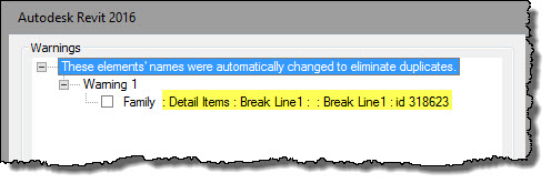
Duplicate marks - Revit will no longer incrementally assign a mark value when placing elements for the following MEP categories: Cable Trays, Cable Tray Fittings, Conduits, Conduit Fittings, Ducts, Duct Fittings, Duct Placeholders, Duct Insulations, Duct Linings, Flex Ducts, Flex Pipes, Pipes, Pipe Fittings, Pipe Placeholders, Pipe Insulations, and Wires.
That should help reduce unnecessary Warnings!
Calculated Values in Tags - This permits us to do the same thing to tags that we've been using in schedules. For example, in a tag I'd like to show the difference between the client required area and the actual area of a room. That wasn't possible without some export/import or Dynamo shenanigans. Now it is possible, right in a tag.

This starts in the Edit Label dialog via a new button, then it is the same as the dialog we've seen in Schedules.

Calculate Options for Columns (in schedules) - You can display minimum values, maximum values, or both minimum and maximum values for calculations in columns.

Auto - Project Base Point to Project Base Point (2016R2) - This positioning option gives us a new way to reconcile files that are started without agreeing in advance how to create our models relative to our own project's origin. We can un-clip the Project Base Point and move it to mark a specific location in our own model. Anyone linking our model can use Auto - Project Base Point to Project Base Point instead. This way our un-clipped PBP location will be used to align their model with our own PBP.
It may be necessary to also move our PBP un-clipped if it isn't already where we've agreed it should be. Keep in mind that Shared Coordinates are still very relevant with respect to survey, site and landscape models and drawings.
Move to Project Base Point - The Move to Project Base Point command moves the link back to the host model Project Base Point in the same manner as the original (project base point to project base point) positioning method. This command is available for any RVT link, regardless of the original positioning method.

Move to Internal Origin - The Move to Internal Origin command moves the selected link back to the host model's internal origin in the same manner as the original (origin to origin) positioning method. This command is also available for any RVT link, regardless of the original positioning method.
Per-User RVT Link Unload (2016R2) - This is relevant to projects using worksharing. When a linked file is unloaded that status is passed along to the central file and then on to other users when the use Reload Latest or Synchronize with Central.
This option will allow us to choose to make this a personal change that does not get passed along to other users. It is one reason we started to use a Workset to manage linked file loading and unloading. With this change the only significant reason to continue using worksets for linked files is for the demand loading of links when we open a project.
Cancel Export and Printing (2016R2) - It has been quite frustrating in the past to be unable to cancel printing when we realize too late that something is wrong. Now a Cancel button allows you to cancel the entire print job or export operation for all selected views and sheets.
Project Browser Scrolling (2016R2) - The project browser scroll location is now remembered when we switch between different projects and families. This should mean we won't have to scroll as much to get back to the same location after switching windows.
View Templates and Schedules - They have expanded how much influence a View Template has over schedule views.

They've added control over Fields, Filters, Sorting/Grouping, and Formatting. I've noticed that the stock templates (project) don't have a View Template for a Schedule (true of 2016 too) which makes it less than obvious how to make a View Template because the Create button is disabled in the View Templates dialog.
The trick is to use Create View Template from View on an existing schedule. Once at least one schedule View Template exists more can be created from within the View Templates dialog, however only for schedules associated with the same category as the original.
If you select a View Template and don't see the new items they can control it means the schedule and the View Template you've selected are incompatible, related to a different category.
Hosted Railings - This is a welcome addition. We can now sketch railings onto the top faces of floors, slabs, slab edges, walls, or roofs. Balusters and railings will adjust to the slope of irregular surfaces, for example a wall that's had Edit Profile used on it. NOTE: They recommend we check railings after upgrading projects.
Generic Connections (Structure) - To facilitate the exchange of information between engineers, detailers, and fabricators about a connection between steel framing elements, Revit supports placing generic steel connections. You can place these to define the relationship between elements which can be used, via parameters, to supply information about the connection, including pictures and links to connection requirements or other information. They can display in drawings and use colors based on approval and/or code checking status parameters for an easier review/approval workflow. If required, they can also be replaced later with detailed steel connections created using an add-in (see next item).
Steel Connections for Revit - This is similar conceptually to what has been done for MEP Fabrication. It is an Autodesk add-in which allows us to view detailed structural connector geometry and to modify additional parameters within the Revit modeling environment.
Reinforcement connectors - Reinforcement connectors are new kind of family. Structural engineers can use schematic connectors to define requirements. Detailers can use them to produce shop drawings. Manufacturers can go into full detail, precisely modeling and representing reinforcement connectors to create installation instructions.
Rebar connectors interact with the rebar that they connect to, facilitating change management. You can add the connectors to groups, assemblies, and partitions with unique coupler numbering. You can also export connectors to various formats.
Variable Rebar Distribution - To fit rebar within complex shapes, you can use rebar sets that can vary along inclined faces. Documentation should be easier with multi-rebar annotations, customizable numbering settings, and accurate schedules that display varying lengths. You can also define inclined rebar sets.
Split columns - The Split Element tool can now split vertical columns at the desired points too.
Wall Joins (2016R2) - We can decide if we want walls to join prior to placing them.

We can also select multiple wall joins and change the configuration of all selected joins to Butt, Miter, or Square Off at the same time.
OTHER STUFF
Preview Family Visibility (2016R2) - The family editor lacked full respect for visibility features like Detail Level and Yes/No parameters associated with a form's Visible parameter. It only made those elements a lighter color (gray). A new View Control Shortcut button allows us to show families they way they will appear in a project setting, all while creating the family in the family editor.

Family Types Dialog (2016R2) - The family types dialog now has a data entry field that allows us to supply criteria to filter the family's parameters. This works on both parameter names and formulas. You'll also find that the text buttons for adding/modifying/deleting types and parameters have been converted into image buttons.

Toposurface Edge Calculations - For conditions where sloped building pads meet other building pads you may recall a sliver of surface might appear between them. Toposurface edges are now calculated based on the building pads, not the overall toposurface. The resulting toposurface should now be more accurate, and hopefully the slivers of toposurface we've seen in the past won't be there.
Keynote Legends - These legends, when set to By Sheet, will now be aware of whether or not a keynote is visible in the view as a result of View Range settings, Design Option settings or Depth Clipping/Far Clipping settings.
In the past Revit displayed a keynote even if it was outside of the View Range, assigned to a different Design Option than the one currently displayed in the view or actually outside of the view’s Depth Clipping / Far Clipping range. Now they won't be included in the schedule if these conditions are true of a given keynote.
Vector Printing for Consistent Colors - They've worked to make Revit more willing to print using the Vector option instead of requiring Raster when we print views that are using the Consistent Colors visual style.
Tangency Lock - This permits us to lock in a relationship between line segments that are tangent to arc's with new icon's that appear when such a condition exists. This should make it easier to deal with arc/line relationships than it has been in the past. We discussed trying to control this series of lines in a thread at AUGI a few years ago. This IS much easier to pull off now.

Column base attachment - The Attach Top/Base command can now attach structural columns to isolated foundations and footings. Adjustments to the foundation height cause the length of the column to adjust accordingly.
Structural foundation parameters - To achieve consistency and use more recognizable terminology, several reporting parameters have been renamed or changed for wall foundations, isolated foundations, and slab foundations.
Energy Analysis - This is a hot topic these days but I don't see a lot of real action regarding these features in offices. Perhaps my own perspective is limited. Regardless Autodesk continues to put a lot of effort into it. To simplify the initial effort (settings we have to manipulate) required to generate an energy analytical model they've made a number of changes.
The Energy Settings dialog has been redesigned so that you only need to specify a location for the model, at the outset. Revit defaults to assigning all other parameter values to arrive at an optimal analysis with minimal input. Many parameters that used to be found in the Energy Settings dialog are now part of the Advanced Energy Settings dialog. You can adjust these settings after performing an initial analysis once you understand the results and decide to refine the analysis.

They've renamed quite a few parameters.
Export to gbXML - The Export to gbXML tool now allows you to choose whether to export the energy analytical model created using energy settings or the model using volumes based on rooms or spaces.
Electrical Settings - We can specify a default rating to use for creating circuits in a model.
Assigning a Distribution System - If there is only one distribution system applicable to an equipment instance, the distribution system is now assigned automatically
New annotation families for MEP - To improve annotation for generic and fabrication parts, several annotation families are now available for tagging ductwork and pipework. (Electrical containment is not currently supported.) You can use tags for offset, elevation, spot elevation, invert elevation (pipework only), set up, and set down to tag generic and fabrication elements. Use the Mechanical Settings dialog to customize the labels for the tags.
Electrical settings - You can specify the load calculation method for how Revit sums electrical loads: Sum True Load and Reactive Load, or Sum Apparent Load and True Load. When upgrading a model, Revit uses the Sum True Load and Reactive Load method as the default.
Temperature Difference family parameter type - The type of parameter is now available for HVAC, Electrical, and Piping families.
Calculate pressure drop for taps - To improve the existing task of calculating pressure drop in a duct system, you can associate an ASHRAE table for duct tap fittings.
Volume calculations - To improve performance pipe system volume calculations are a background process now.
Display of ducts - Revit will regenerate duct layouts only for what is visible in the drawing area. If duct appears very small in the drawing area, it will display as simplified lines, regardless of the detail level assigned to the view. (similar to what they are doing for walls now too)
Dynamo Integration - You'll find this installed as part of Revit and it's not on the Add-Ins tab anymore, it is on the Manage tab. I find that choice confusing personally.

After installing Revit Dynamo reports version 0.9.1.4062 (up-to-date). However the icon for Update available turned green while I was looking at the dialog. When I returned to About Dynamo it reported a different build number available as well as the green cloud icon that changed a moment earlier.

You'll just need to pay attention to this after installing Revit. Dynamo is dynamic, it's changing and improving on a daily basis.
Revit Fabrication They've made quite a lot of changes to this ongoing integration between design and fabrication. This is a list of the information they've provided in the what's new documentation at the help site.
Bent fabric reinforcement - Sketch bent sheets to accommodate different shapes of concrete hosts. You can edit them later to adjust to any change.
Constrained Rebar placement - A new graphical constraints manager enhances precise rebar placement. You can place standard rebar shapes that snap to adjacent standard rebar, or you can constrain them to host faces. The user interface highlights each rebar segment that can be constrained, along with available targets. You can modify dimensions to adjust the rebar position. The snap constraint maintains its relationship when you place, move, drag, or copy rebar.
Graphical Rebar Constraint Editing - A new in-canvas editor replaces the Rebar Constraints dialog.
Revit - Robot Integration - Using the Revit - Robot link, the new results for required reinforcement: transverse density can be exported to Revit. You can display diagrams of transverse density using Results Explorer.
SUBTLE STUFF
Annotation Tags - If you choose to pin an annotation tag, then its text box will remain in the same location if its host element is moved. The text of a tag will not move when you switch the leader on and off when it is using Free end. When you switch from Free end to Attached end the leader will not change its shape.
Filter voids and solids (2016R2) - You can specifically isolate void and solid geometry when using the Filter tool in the Family Editor.
Editing Commands in Perspective Views (2016R2) - We can use Copy to Clipboard with Paste Aligned and the Copy command in Camera Views that are using the perspective option.
Spot Slope (2016R2) - You can now place a spot slope annotation that is referencing an element in a linked model.
View Range - A keyboard shortcut is assigned now: VR. If you select a Plan Region first using VR will open the view range dialog for it instead.
View Range Dialog (2016R2) - It has a Show/Hide option to expand to show a graphic explanation of the separate sections of View Range. READ the POST.
Underlay User Interface (2016R2) - I wrote about this change earlier this year when it became available with R2. They changed the language associated with describing the settings for Underlay. They also moved it into it own section (Group) in the Properties Palette.
Point Cloud Visibility - We can control the visibility of individual scan locations and scan regions in each view. This allows us to hide point cloud information that is not relevant in a given view. It should also help improve performance.
Revit.ini setting for CaBaGGe - A new setting in Revit.ini allows you to control the CaBaGGe framework, which improves the performance of Revit when navigating views. That stands for Camera Based GRep Generation (CaBaGGe) and it is intended to allow us to navigate highly detailed Revit models more quickly, by not spending time on things that we don't see. They recommend disabling CaBaGGe if you find that the pan/zoom/view-manipulation time is distracting.
Revisions (2016R2) - When Numbering is set to Per Project, you'll see a new Revision Number column displays the actual revision number that will be generated based on the Sequence, Numbering scheme, and Numbering options. Naturally this won't work if the project is using numbering Per Sheet.

When you open the Revisions on Sheet dialog there is now a Revision column which includes both the revision sequence information and the revision description. A new Date column displays the revision's date.

Filters Dialog (2016R2) - The Filters dialog has been changed a bit. You find filters are listed alphabetically and sorted separately using headings for rule-based and selection-based filters. Earlier I mentioned that we'll find Reference Planes are in the list of categories a Filter can see too.

Detach from Central File (2016R2) - Revit supplies _detached suffix to the file's name when you use Detach from Central and save the file. I wrote about this earlier.

Modify Patterns Dialog - It is re-sizable now, nuff said.
Object Styles (2016R2) - In the Object Styles dialog, you can select and delete multiple subcategories at once. Use CTRL or SHIFT keys to add or remove (select/deselect) subcategories, and then click Delete.
UI Assign Labels - When we want to assign a label (parameter) to a dimension string the user interface has moved to the ribbon now. I think this further undermines the significance of the Options Bar to our workflow (good or bad?). Click the little button (looks like an old Mac) to create a new parameter or choose and existing one from the drop-down list. Even the check box for Instance Parameter is here now instead of the Options Bar.

Upgrade Information - There is a dedicated section in the Help Documentation for Upgrade Information. It will be helpful to see which features we need to watch closely during and after the upgrade to make sure it completed successfully and the results are satisfactory.
Export to FBX - When exporting a 3D model view to FBX, select one of these formats to ensure import compatibility: FBX Files for import in 2016+ version products, or FBX 2015 and Previous for import in 2015 and earlier version products.
FormIt 360 Converter - This add-in is now installed with Revit and available on the Add-Ins tab. It can be used to convert FormIt 360 files for use with Revit or the reverse, Revit files for use with FormIt 360.
Collaboration for Revit (C4R) - This is installed in Revit 2017 automatically. This eliminates the need to install something if/when a user then subscribes to C4R. It is intended to reduce the need for IT effort and involvement.
Software Product Package Changes - Revit Arch, Revit MEP, or Revit Structure are no longer sold as individual products. All Revit users now get Revit in one Box which contains ALL of the features of the separate versions.
That's a lot to sink your teeth into, have fun getting acquainted with 2017!
P.S. There are many changes and additions to the API for Revit. You'll need to refer to the related SDK (software developer kit) for those details, sorry.
Edit: (April 17th) - The BIM Thoughts episode #30, is a podcast with Bill Debevc (it's Bill's podcast), Carla Edwards, Paul Aubin and me. We recorded it on Sunday (April 17th) and discussed some of the new features described below.
Last night I was able to download and install Building Design Suite 2017 from my Autodesk subscription account. You might like to read Tim Waldock's blog post (The Revit Cat) about installing it.
With little fanfare Revit 2017 is here, brandishing a slightly changed big R logo.
In past years I've proposed a What's New in Revit session for RTC Australasia. It has usually been accepted and then I often presented it for RTC North America too. Creating a session like that is a great way to get better acquainted with the new features each year. Last year I promised myself (and family) I wouldn't submit for any speaking engagements in the coming year (2016). Besides, after more than ten years of this, I feel like I have less I need to stand up in front of people and say.
As a part of the crew for the Revit Technology Conference (RTC Events) I also see class proposals for a great many people who really want to say what's on their mind. I'd rather they all take their turn at the microphone and I'll sit down, listen and learn from them.
That written I decided to compile my own review of the new features and enhancements in a blog post. I'll still do what I've done in the past and tackle features with dedicated posts as the new Revit season progresses. I think that individual posts make features a bit easier to digest; hopefully they compliment a summary post like this one.
In my RTC sessions I've repackaged the new stuff into my own three categories of Stuff; Big Stuff, Other Stuff and Subtle Stuff. Autodesk has their own interpretation of what are big new features and sometimes I agree.
Before I get on with it, I need to mention that a fair portion of what is new has already been seen, and put into play by Autodesk customers with active subscriptions. Autodesk released Revit 2016 R2 like they did with Revit 2015 the year before. The special R2 version gives us early access to some of Revit 2017 features that were code complete and did not require a file format change, which necessitates an upgrade of files. We'll see a need for upgrading from 2016 to 2017 files but not from 2016 to 2016 R2 files. Okay, on to the list!
BIG STUFF
New Features Videos - Start with these videos provided as part of the help documentation if you prefer watching videos to reading my blog post.
Help Documentation links for What's New in Revit 2017
Architectural Enhancements in Revit 2017
Mechanical, Electrical, and Plumbing Engineering Enhancements in Revit 2017
Structural Engineering Enhancements in Revit 2017
Multi-Disciplinary Enhancements in Revit 2017 (called Platform in the past)
New in Revit 2016 R2 (features released with R2 late last year)
Text Editor - A top ten wish list item since Revit 1.0 has finally been tackled. It's apparently a lot harder to create a full featured text editor than we users think. We'll have to see how it is received.
We'll be able to create indented lists with a bit more control now and we can place just a leader (empty text). Look for tomorrow's post, I'll cover this feature more then. You'll definitely want to look closely at this change.

Depth Cueing - This is another frequently requested concept. In Architectural and Coordination discipline views this allows you to apply a gradient override to make it more obvious which elements are farthest away compared to the elements that are closest to the cut plane of the view.
It applies to model elements, and graphic display effects, such as shadows and sketchy lines. It is not applied to annotation elements, line weight, line work, background images, or background color. When you've turned on and adjusted the settings you can export the view to an image file, print the view (uses raster processing ONLY) and/or add the view to a sheet (print/export that instead).

Try it out before you decide raster printing isn't going to cut it for you.
Occlusion Culling (2016R2) - The Graphics tab in the Options dialog offers the new setting: Draw visible elements only. It will be most noticeable in 3D views.
Color Fills (2016R2) - Any processing required to update or display these are now a background process (see next item).
Background Processess (2016R2) - A new Status Bar icon by the Selection options will let us review active background processes.

Display of walls - Revit will regenerate walls only for those visible within the drawing area. In addition, if a wall appears very small in the drawing area, it displays as simplified lines, regardless of the detail level assigned to the view. MEP users will see that they are doing the same thing with Duct.
Rendering - The change over is complete, Mental Ray is out. Autodesk Raytracer is now used for all rendering functions so the option to select a rendering engine has been removed. When you export a walkthrough, if Visual Style is set to Rendering, the Autodesk Raytracer rendering settings specified for the walkthrough's view are used for export. Rendering settings are saved with each view's properties.
Autodesk Raytracer is used when you render a material preview. You can select draft or production quality. When you upgrade a model, the rendering settings that were specified for the NVIDIA mental ray engine are mapped as closely to the appropriate settings for the new engine as possible.
There is a new Background style in the Rendering dialog called Transparent. You'll want to use that when exporting to PNG or TIFF formats for further processing in Photoshop.

Global Parameters (2016R2) - This permits us to create a parameter at the top of a project and then associate it with individual element's parameters. They can also be associated with dimensions similar to assigning a parameter to a dimension in the family editor. For example, a standard corridor width requirement can be associated with any dimension we use between corridor walls, like this.

We can associate global parameters with a type property for an element and with instance or type project parameters. They can also be assigned to a group (parameter group in Properties Palette). They can be moved and sorted within their assigned group(s). A schedule can be Filtered by a global parameter to find all elements that have a global parameter association or are missing that association. Like other constraints, use right-click Show Label in a view to see how the parameter is related to elements in the project. We can transfer global parameters between projects.
Reference Planes - We can now create different Reference Plane sub-categories which can be given different graphic properties. This is an example of it in the Family Editor.

In a project it might look this if we create a unique subcategory for Building Edges and Roof Drains.

One thing to be VERY careful about is that Reference Plane subcategories created in a family are added to projects if they aren't already in the Project. That could create quite a mess if/ (or more likely when) family editors go nuts with this feature. This one scares me quite a bit.

In 2016 R2 we can provide a Name for a Reference Plane directly in-canvas after selecting it, it looks like this.

Reference Planes and Filters - Like Grids and Levels we can now use Filters to manage Reference Planes because the category has been added to the available categories they see.

In-Place Stairs: This opens the door to creating custom stairs that don't use the stair tool itself. They have added Stair related categories to the list of available family categories for In-Place geometry.
Combine Parameters (in Schedules) - This is the often requested ability to concatenate parameters values into a single column. The schedule Properties dialog has seen some cosmetic changes, note the new Combine Parameters button.

We see the new smaller buttons replacing the larger and clearer buttons of old. It's a cleaner interface but I miss the clearer labeling of such things. Now if I'm not sure what something is I have to pause for a tool tip to appear. I also get the New and Modify buttons confused with each other ALL the time. When we use Combine Parameters the dialog looks like this for a Room Schedule.

This is combining width and height into a single size parameter for a Door Schedule.

Another very interesting possibility is to combine different parameters for the same values when different families are displaying the same information but have different parameter names, because they came from different family creators. Here's combining three versions of width parameters into a single column, three families using three different shared parameters for the same thing, you can see I left each parameter's name in the heading.

I found it interesting that I can even combine parameters assigned to different Types of Parameter, like length and text. This is an example where I've combined two text parameters and one length parameter all intending to say the same thing, however impractical it will be to deal with the units of that mixture, or lack thereof.

This means we can create a VAV Schedule based on different families from different manufacturers and combine their different manner of Horsepower (or similar) parameter value into a single column. VERY interesting!
Duplicate marks - Revit will no longer incrementally assign a mark value when placing elements for the following MEP categories: Cable Trays, Cable Tray Fittings, Conduits, Conduit Fittings, Ducts, Duct Fittings, Duct Placeholders, Duct Insulations, Duct Linings, Flex Ducts, Flex Pipes, Pipes, Pipe Fittings, Pipe Placeholders, Pipe Insulations, and Wires.
That should help reduce unnecessary Warnings!
Calculated Values in Tags - This permits us to do the same thing to tags that we've been using in schedules. For example, in a tag I'd like to show the difference between the client required area and the actual area of a room. That wasn't possible without some export/import or Dynamo shenanigans. Now it is possible, right in a tag.

This starts in the Edit Label dialog via a new button, then it is the same as the dialog we've seen in Schedules.

Calculate Options for Columns (in schedules) - You can display minimum values, maximum values, or both minimum and maximum values for calculations in columns.

Auto - Project Base Point to Project Base Point (2016R2) - This positioning option gives us a new way to reconcile files that are started without agreeing in advance how to create our models relative to our own project's origin. We can un-clip the Project Base Point and move it to mark a specific location in our own model. Anyone linking our model can use Auto - Project Base Point to Project Base Point instead. This way our un-clipped PBP location will be used to align their model with our own PBP.
It may be necessary to also move our PBP un-clipped if it isn't already where we've agreed it should be. Keep in mind that Shared Coordinates are still very relevant with respect to survey, site and landscape models and drawings.
Move to Project Base Point - The Move to Project Base Point command moves the link back to the host model Project Base Point in the same manner as the original (project base point to project base point) positioning method. This command is available for any RVT link, regardless of the original positioning method.

Move to Internal Origin - The Move to Internal Origin command moves the selected link back to the host model's internal origin in the same manner as the original (origin to origin) positioning method. This command is also available for any RVT link, regardless of the original positioning method.
Per-User RVT Link Unload (2016R2) - This is relevant to projects using worksharing. When a linked file is unloaded that status is passed along to the central file and then on to other users when the use Reload Latest or Synchronize with Central.
This option will allow us to choose to make this a personal change that does not get passed along to other users. It is one reason we started to use a Workset to manage linked file loading and unloading. With this change the only significant reason to continue using worksets for linked files is for the demand loading of links when we open a project.
Cancel Export and Printing (2016R2) - It has been quite frustrating in the past to be unable to cancel printing when we realize too late that something is wrong. Now a Cancel button allows you to cancel the entire print job or export operation for all selected views and sheets.
Project Browser Scrolling (2016R2) - The project browser scroll location is now remembered when we switch between different projects and families. This should mean we won't have to scroll as much to get back to the same location after switching windows.
View Templates and Schedules - They have expanded how much influence a View Template has over schedule views.

They've added control over Fields, Filters, Sorting/Grouping, and Formatting. I've noticed that the stock templates (project) don't have a View Template for a Schedule (true of 2016 too) which makes it less than obvious how to make a View Template because the Create button is disabled in the View Templates dialog.
The trick is to use Create View Template from View on an existing schedule. Once at least one schedule View Template exists more can be created from within the View Templates dialog, however only for schedules associated with the same category as the original.
If you select a View Template and don't see the new items they can control it means the schedule and the View Template you've selected are incompatible, related to a different category.
Hosted Railings - This is a welcome addition. We can now sketch railings onto the top faces of floors, slabs, slab edges, walls, or roofs. Balusters and railings will adjust to the slope of irregular surfaces, for example a wall that's had Edit Profile used on it. NOTE: They recommend we check railings after upgrading projects.
Generic Connections (Structure) - To facilitate the exchange of information between engineers, detailers, and fabricators about a connection between steel framing elements, Revit supports placing generic steel connections. You can place these to define the relationship between elements which can be used, via parameters, to supply information about the connection, including pictures and links to connection requirements or other information. They can display in drawings and use colors based on approval and/or code checking status parameters for an easier review/approval workflow. If required, they can also be replaced later with detailed steel connections created using an add-in (see next item).
Steel Connections for Revit - This is similar conceptually to what has been done for MEP Fabrication. It is an Autodesk add-in which allows us to view detailed structural connector geometry and to modify additional parameters within the Revit modeling environment.
Reinforcement connectors - Reinforcement connectors are new kind of family. Structural engineers can use schematic connectors to define requirements. Detailers can use them to produce shop drawings. Manufacturers can go into full detail, precisely modeling and representing reinforcement connectors to create installation instructions.
Rebar connectors interact with the rebar that they connect to, facilitating change management. You can add the connectors to groups, assemblies, and partitions with unique coupler numbering. You can also export connectors to various formats.
Variable Rebar Distribution - To fit rebar within complex shapes, you can use rebar sets that can vary along inclined faces. Documentation should be easier with multi-rebar annotations, customizable numbering settings, and accurate schedules that display varying lengths. You can also define inclined rebar sets.
Split columns - The Split Element tool can now split vertical columns at the desired points too.
Wall Joins (2016R2) - We can decide if we want walls to join prior to placing them.

We can also select multiple wall joins and change the configuration of all selected joins to Butt, Miter, or Square Off at the same time.
OTHER STUFF
Preview Family Visibility (2016R2) - The family editor lacked full respect for visibility features like Detail Level and Yes/No parameters associated with a form's Visible parameter. It only made those elements a lighter color (gray). A new View Control Shortcut button allows us to show families they way they will appear in a project setting, all while creating the family in the family editor.

Family Types Dialog (2016R2) - The family types dialog now has a data entry field that allows us to supply criteria to filter the family's parameters. This works on both parameter names and formulas. You'll also find that the text buttons for adding/modifying/deleting types and parameters have been converted into image buttons.

Toposurface Edge Calculations - For conditions where sloped building pads meet other building pads you may recall a sliver of surface might appear between them. Toposurface edges are now calculated based on the building pads, not the overall toposurface. The resulting toposurface should now be more accurate, and hopefully the slivers of toposurface we've seen in the past won't be there.
Keynote Legends - These legends, when set to By Sheet, will now be aware of whether or not a keynote is visible in the view as a result of View Range settings, Design Option settings or Depth Clipping/Far Clipping settings.
In the past Revit displayed a keynote even if it was outside of the View Range, assigned to a different Design Option than the one currently displayed in the view or actually outside of the view’s Depth Clipping / Far Clipping range. Now they won't be included in the schedule if these conditions are true of a given keynote.
Vector Printing for Consistent Colors - They've worked to make Revit more willing to print using the Vector option instead of requiring Raster when we print views that are using the Consistent Colors visual style.
Tangency Lock - This permits us to lock in a relationship between line segments that are tangent to arc's with new icon's that appear when such a condition exists. This should make it easier to deal with arc/line relationships than it has been in the past. We discussed trying to control this series of lines in a thread at AUGI a few years ago. This IS much easier to pull off now.

Column base attachment - The Attach Top/Base command can now attach structural columns to isolated foundations and footings. Adjustments to the foundation height cause the length of the column to adjust accordingly.
Structural foundation parameters - To achieve consistency and use more recognizable terminology, several reporting parameters have been renamed or changed for wall foundations, isolated foundations, and slab foundations.
- Isolated foundations - The Offset instance parameter is now Height Offset From Level.
- Slab foundations - The Default Thickness parameter for filters, tags, and schedules is now Foundation Thickness.
- Elevation reporting - Top/Bottom Elevations parameters are now measured in relation to the Project Base Point.
- Elevation at Top/Bottom Survey - The Elevation at Top/Bottom Survey parameters for filters, tags, and schedules are measured by the shared Survey Point elevation.
Energy Analysis - This is a hot topic these days but I don't see a lot of real action regarding these features in offices. Perhaps my own perspective is limited. Regardless Autodesk continues to put a lot of effort into it. To simplify the initial effort (settings we have to manipulate) required to generate an energy analytical model they've made a number of changes.
The Energy Settings dialog has been redesigned so that you only need to specify a location for the model, at the outset. Revit defaults to assigning all other parameter values to arrive at an optimal analysis with minimal input. Many parameters that used to be found in the Energy Settings dialog are now part of the Advanced Energy Settings dialog. You can adjust these settings after performing an initial analysis once you understand the results and decide to refine the analysis.

They've renamed quite a few parameters.
- Analysis Mode is now Mode
- Core Offset is now Perimeter Zone Depth
- Divide Perimeter Zones is now Perimeter Zone Division.
- Conceptual Constructions is now Conceptual Types
- Building Construction is now Schematic Types
- Include Thermal Properties is now Detailed Elements
Export to gbXML - The Export to gbXML tool now allows you to choose whether to export the energy analytical model created using energy settings or the model using volumes based on rooms or spaces.
Electrical Settings - We can specify a default rating to use for creating circuits in a model.
Assigning a Distribution System - If there is only one distribution system applicable to an equipment instance, the distribution system is now assigned automatically
New annotation families for MEP - To improve annotation for generic and fabrication parts, several annotation families are now available for tagging ductwork and pipework. (Electrical containment is not currently supported.) You can use tags for offset, elevation, spot elevation, invert elevation (pipework only), set up, and set down to tag generic and fabrication elements. Use the Mechanical Settings dialog to customize the labels for the tags.
Electrical settings - You can specify the load calculation method for how Revit sums electrical loads: Sum True Load and Reactive Load, or Sum Apparent Load and True Load. When upgrading a model, Revit uses the Sum True Load and Reactive Load method as the default.
Temperature Difference family parameter type - The type of parameter is now available for HVAC, Electrical, and Piping families.
Calculate pressure drop for taps - To improve the existing task of calculating pressure drop in a duct system, you can associate an ASHRAE table for duct tap fittings.
Volume calculations - To improve performance pipe system volume calculations are a background process now.
Display of ducts - Revit will regenerate duct layouts only for what is visible in the drawing area. If duct appears very small in the drawing area, it will display as simplified lines, regardless of the detail level assigned to the view. (similar to what they are doing for walls now too)
Dynamo Integration - You'll find this installed as part of Revit and it's not on the Add-Ins tab anymore, it is on the Manage tab. I find that choice confusing personally.

After installing Revit Dynamo reports version 0.9.1.4062 (up-to-date). However the icon for Update available turned green while I was looking at the dialog. When I returned to About Dynamo it reported a different build number available as well as the green cloud icon that changed a moment earlier.

You'll just need to pay attention to this after installing Revit. Dynamo is dynamic, it's changing and improving on a daily basis.
Revit Fabrication They've made quite a lot of changes to this ongoing integration between design and fabrication. This is a list of the information they've provided in the what's new documentation at the help site.
- Convert design intent to fabrication parts - You can convert generic, design-intent Revit parts to LOD 400 fabrication parts.
- Route and Fill - To simplify the process for completing a fabrication model, use the Route and Fill command to step through possible routing solutions.
- Quick Connect - To simplify the process for filling a gap between a fitting and a straight, use the Quick Connect command.
- Trim/extend - To simply the process for filling a gap between two straights, use the Trim/Extend tool.
- Swap fabrication parts - Use the Type Selector to quickly swap fabrication parts.
- Fabrication parts optimization - To help optimize fabrication ductwork layouts, you can use in-canvas controls to reposition short straight segments and to extend fitting extensions. Additionally, you can review warnings to find fittings that are longer than specification-defined lengths.
- Hanger bearer position -To avoid clashes in the model, use the hanger controls to modify the length and position of the hanger bearer and its corresponding rod location.
- Hanger placement - You can place a fabrication hanger on the straight portion of a fitting extension. Hangers can be placed on other hangers to model trapeze conditions or in free space.
- Tag fabrication parts - To support workflows for construction documentation for fabrication, additional fabrication parameters are available for tagging fabrication parts.
- Fabrication parameters - To improve tagging, scheduling, and filtering capabilities for MEP fabrication modelling, several parameters are now available for fabrication parts.
- Fabrication family categories - To improve annotation, scheduling, and filtering capabilities for MEP fabrication modelling, family categories have been added for MEP Fabrication Containment, MEP Fabrication Ductwork, MEP Fabrication Hangers, and MEP Fabrication Pipework.
- Hidden lines for fabrication parts - To improve documentation, fabrication parts now display hidden lines.
- Insulation and lining - To improve documentation, fabrication parts now display separate sub-components for insulation and lining for duct and pipe elements, allowing more control of display properties.
- Rise drop symbols - This enhancement supports coordination between fabrication models in Revit and the Autodesk Fabrication products (CADmep, ESTmep, and CAMduct). Rise drop symbols for a fabrication run in Revit are defined in the Autodesk Fabrication products, and are mapped to the rise drop symbols used for duct, piping, and electrical containment systems in Revit.
- Tool Tips for fabrication parameters in the Properties palette - Tool tips now provide descriptions for fabrication parameters in the Properties palette.
- Fabrication settings - When you specify a fabrication configuration, you can also specify a fabrication profile.
- MEP Fabrication Content for Revit - This fabrication configuration is now available as part of the Revit installation.
Bent fabric reinforcement - Sketch bent sheets to accommodate different shapes of concrete hosts. You can edit them later to adjust to any change.
Constrained Rebar placement - A new graphical constraints manager enhances precise rebar placement. You can place standard rebar shapes that snap to adjacent standard rebar, or you can constrain them to host faces. The user interface highlights each rebar segment that can be constrained, along with available targets. You can modify dimensions to adjust the rebar position. The snap constraint maintains its relationship when you place, move, drag, or copy rebar.
Graphical Rebar Constraint Editing - A new in-canvas editor replaces the Rebar Constraints dialog.
Revit - Robot Integration - Using the Revit - Robot link, the new results for required reinforcement: transverse density can be exported to Revit. You can display diagrams of transverse density using Results Explorer.
SUBTLE STUFF
Annotation Tags - If you choose to pin an annotation tag, then its text box will remain in the same location if its host element is moved. The text of a tag will not move when you switch the leader on and off when it is using Free end. When you switch from Free end to Attached end the leader will not change its shape.
Filter voids and solids (2016R2) - You can specifically isolate void and solid geometry when using the Filter tool in the Family Editor.
Editing Commands in Perspective Views (2016R2) - We can use Copy to Clipboard with Paste Aligned and the Copy command in Camera Views that are using the perspective option.
Spot Slope (2016R2) - You can now place a spot slope annotation that is referencing an element in a linked model.
View Range - A keyboard shortcut is assigned now: VR. If you select a Plan Region first using VR will open the view range dialog for it instead.
View Range Dialog (2016R2) - It has a Show/Hide option to expand to show a graphic explanation of the separate sections of View Range. READ the POST.
Underlay User Interface (2016R2) - I wrote about this change earlier this year when it became available with R2. They changed the language associated with describing the settings for Underlay. They also moved it into it own section (Group) in the Properties Palette.
Point Cloud Visibility - We can control the visibility of individual scan locations and scan regions in each view. This allows us to hide point cloud information that is not relevant in a given view. It should also help improve performance.
Revit.ini setting for CaBaGGe - A new setting in Revit.ini allows you to control the CaBaGGe framework, which improves the performance of Revit when navigating views. That stands for Camera Based GRep Generation (CaBaGGe) and it is intended to allow us to navigate highly detailed Revit models more quickly, by not spending time on things that we don't see. They recommend disabling CaBaGGe if you find that the pan/zoom/view-manipulation time is distracting.
Revisions (2016R2) - When Numbering is set to Per Project, you'll see a new Revision Number column displays the actual revision number that will be generated based on the Sequence, Numbering scheme, and Numbering options. Naturally this won't work if the project is using numbering Per Sheet.

When you open the Revisions on Sheet dialog there is now a Revision column which includes both the revision sequence information and the revision description. A new Date column displays the revision's date.

Filters Dialog (2016R2) - The Filters dialog has been changed a bit. You find filters are listed alphabetically and sorted separately using headings for rule-based and selection-based filters. Earlier I mentioned that we'll find Reference Planes are in the list of categories a Filter can see too.

Detach from Central File (2016R2) - Revit supplies _detached suffix to the file's name when you use Detach from Central and save the file. I wrote about this earlier.

Modify Patterns Dialog - It is re-sizable now, nuff said.
Object Styles (2016R2) - In the Object Styles dialog, you can select and delete multiple subcategories at once. Use CTRL or SHIFT keys to add or remove (select/deselect) subcategories, and then click Delete.
UI Assign Labels - When we want to assign a label (parameter) to a dimension string the user interface has moved to the ribbon now. I think this further undermines the significance of the Options Bar to our workflow (good or bad?). Click the little button (looks like an old Mac) to create a new parameter or choose and existing one from the drop-down list. Even the check box for Instance Parameter is here now instead of the Options Bar.

Upgrade Information - There is a dedicated section in the Help Documentation for Upgrade Information. It will be helpful to see which features we need to watch closely during and after the upgrade to make sure it completed successfully and the results are satisfactory.
Export to FBX - When exporting a 3D model view to FBX, select one of these formats to ensure import compatibility: FBX Files for import in 2016+ version products, or FBX 2015 and Previous for import in 2015 and earlier version products.
FormIt 360 Converter - This add-in is now installed with Revit and available on the Add-Ins tab. It can be used to convert FormIt 360 files for use with Revit or the reverse, Revit files for use with FormIt 360.
Collaboration for Revit (C4R) - This is installed in Revit 2017 automatically. This eliminates the need to install something if/when a user then subscribes to C4R. It is intended to reduce the need for IT effort and involvement.
Software Product Package Changes - Revit Arch, Revit MEP, or Revit Structure are no longer sold as individual products. All Revit users now get Revit in one Box which contains ALL of the features of the separate versions.
That's a lot to sink your teeth into, have fun getting acquainted with 2017!
P.S. There are many changes and additions to the API for Revit. You'll need to refer to the related SDK (software developer kit) for those details, sorry.