Monday, January 23, 2012

Color Fill Legends Mixing with Stairs and Railings

David Light wrote a post about getting stairs to display better when color fill legends are involved. Then Brian Mackey wrote a post to offer another solution. David's approach involves using a solid fill and matching color to "blend" the color fill and the solid fill colors. Brian's involves using the new "Ghost Surfaces" feature.

To offer my two cents I wrote a comment to David's post after reading his. I mentioned what happens when we use the "Transparent" option for categories in Visibility/Graphics or using Override Graphics in View feature > By Element.

This is what you see on screen (using the "Transparent" option to "Override Graphics in View > By Element")(uh oh):


And this is what you get when you print (oh? okay):


Intrigued because I didn't bother to try the approach Brian suggested, I tried it. Using the "Ghost Surfaces" option to "Override Graphics in View > By Element" you see this on screen (looking good):


This is what you get when you print (oh, not so good):


Tag...you guys are "it"! :)

Export a Shared Parameter

A more recent post with images is POSTED HERE now.

or alternate title, "Road to Recovery"

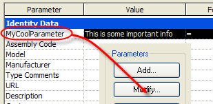
When you don't have access to the original Shared Parameter's file there are two ways to get to it, via a family or in a schedule. Either way you need to be able to “touch” the parameter so you can use the Export option for shared parameters. Revit will add the parameter to the current shared parameter file you are using.

In a family you need to open Family Types, select the parameter, choose the Modify button.

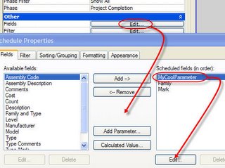
In a project schedule you need to take a look at the view properties for the schedule, view the fields, pick the parameter, then click Edit.

In either case you just need to click Export and Revit will warn you that it will add it to the current shared parameter file you are using.


If the Export button is not active it is because you don’t have a shared parameter file selected yet. You’ll need to do so first. Go to the Manage Ribbon > Settings panel > Shared Parameters button, browse to find it or create one from scratch.

The only family type that doesn't play along with this scenario is titleblocks. Shared parameters that are used in titleblocks must be "connected" to a project by adding the shared parameter to the project as a project parameter too, since titleblocks are sort of a "tag" for views.

Friday, January 20, 2012

Parameter Pecking Order or Priority

There is no preference applied to one over another. A Shared Parameter is no different than a Project Parameter... a parameter is a parameter. How they are defined and shared between projects and families is different.

A family parameter is confined to the family. It can be seen and altered from within a project but not scheduled or tagged unless it is a built in parameter (created by Autodesk's Revit team) like those listed under the Identity group.

A Project Parameter is part of a project and applied broadly to a single category or even categories of families so that it can be scheduled, but not tagged.

A shared parameter bridges both, acting as a dictionary (the shared parameter file) by storing common definitions so they can be reused (yes "shared") in other projects or families. When you add a family or project parameter using a shared parameter (definition from the dictionary) it is really just another parameter but it has expanded possibilities because it is "shared".

If you add a family parameter to a door called "My Parameter" and add another Project Parameter to your project called "My Parameter" (applied to door category) and create a Shared Parameter (added to door and project) called "My Parameter" you'll end up with four (4) parameters called "My Parameter" in the project. All will be listed in the properties of the door family in the project. A couple will be listed in the door family itself when open in the family editor. A couple will be available in the Schedule Properties dialog. The name we "see" for a parameter isn't really what makes it unique. They have a GUID (globally unique Identifier).

Short answer...doesn't matter how you add the parameter, Revit doesn't pay more attention to one over another or deal with one kind first, then another...no pecking order.

Thursday, January 19, 2012

Shared Parameter Czar

I encourage people to have a single point of contact (POC) with Shared Parameters. If a project needs a new parameter then see the POC for getting it added to the office Shared Parameters. Often this interaction makes a team aware of the fact that such a parameter exists or a similar one does for much the same purpose. Same goes for firms with more than one office. They just need to share a read only copy of the shared parameter file for each office so they can use them too. Call the POC the SP Czar or King or Gov... put one person who has the best handle on what exists and what's possible and what it's all about... Alfie.

If you have job or client specific sets of parameters, just create a separate group for them. Avoid having job specific things for generic things like length, width etc. Often this starts with documentation requirements, what has to appear in a schedule for example. If you and the office can define what information must appear in that kind of documentation you can map out a parameter strategy. Keep in mind that this situation is happening in every office and for every person that makes content... I think of it as the great big can o' worms that Revit and BIM have spun the lid off and hasn't resolved.

Wednesday, January 18, 2012

Press and Drag

The Autodesk blog "Inside the Factory" is asking about the Press and Drag option. Using this software for as long as I have I'm quite unhappy when the option is off. Maybe it's minor or strange, and to some irksome or even dangerous, but I'm very used to and happy to use it. So far the comments on their post seem to be running in favor of removing or "blunting" it somehow. According to one comment, I'm nuts for using or liking it.

The only time I get frustrated with it is with linked files. Revit's odd preference for "seeing" and therefore selecting linked elements over the native elements is something that ought to be fixed instead. Removing the Press and Drag feature should not come as a result of other issues.

I find it interesting that people who normally count clicks are "happy" to add more clicks for this item. I use press and drag for so many things, dimensions, text, tags, equipment, duct/pipe runs, walls, doors/windows, viewports on sheets, practically everything at some point. When things need to be precise it isn't the correct approach but so much of what we do during design and documentation can be adjusted more readily with it on.

    My vote is leave "my" Press and Drag alone.

If people don't want to use it, that's what the check box is for and it can be preset to "off" via the Revit.ini file already. Don't like it, don't use it, please don't make my choice for me.

Revit History Lesson

If you are interested in a little history of Revit wander over to Jeremy's blog The Building Coder. Cool!

The Shared Parameter File has no Relationships

I frequently read about or hear questions about this concept that generally assume or expect that there is some inherent (permanent or connected) relationship between a shared parameter file and the use of such a parameter in a project or family.

The shared parameter file has no active relationship (no link, no "xref", no lookup) with your families or projects so there is no risk of someone running off with it, or it getting deleted. The shared parameter file is only used like a "dictionary". We/Revit uses it to "look up" a parameter definition to apply it to a family or project. Thereafter when Revit encounters it in the project it knows what it means. Thus no active connection to the parameter in the file itself.

If someone loses the shared parameter file it is possible to export shared parameters from projects that have them to restore their definition to a new "dictionary". You can read this post to find out how.

Tuesday, January 17, 2012

AUGI Survey Says

AUGI has a "curiosity" survey running right now. Visit the site and take a look at the right hand side of the page, scroll down a bit.


The option I need isn't there..."Brochure inside AutoCAD Software Box"... that makes me a bit of an old timer. I first heard about AUGI in the late 90's. I joined a couple years before my first AU and participated in the "Guilds", email based community support network. You sent a question to a guild email address and it got passed on to everyone in the guild and whoever had time, an interest and hopefully the answer responded.

If you are interested in helping AUGI discover how people are finding out about the group, wander over there and check off the one that best fits you.

RevitCat - Tim Joins the Ranks

Tim Waldock presented a session at RTCUSA last year and posted a teaser video of his session. He's decided to write some of his experimentation and experiences on his new blog RevitCAT. You can watch the videos he's posted in his first few posts so far. He's planning on another video teaser for the next RTC event(s) assuming that acceptance is forthcoming...which I'd be surprised if it wasn't. Another blog for the reader!

Here's my own teaser for his blog, he posted this at You Tube last year too.


Monday, January 16, 2012

Conduit from Face Gotcha!

The other day I made what I thought was a simple distribution box, the kind that is really a "junction" box that sits in a ceiling to provide some wire management access. A pull box with a nice door. No problem. To test it out I tried to run some conduit to it. I expected the surface to highlight when I put the cursor over the edge of the box. Nothing. I selected the box and saw the conduit connectors, right-click > choose Draw conduit from face...nothingness. A blank stare from Revit...me staring blankly at Revit. Huh?

Time for a break...

After some dinner I fired it all back up and some clarity returned. Ahh, I used visibility settings on the "box" and un-checked the Plan option.


I used Symbolic Lines to show the box in plan instead. That was the gotcha...if the solid form/face that is the conduit connectors host isn't visible in the plan view the Draw Conduit from Face tool says, "huh?!?". It's kind of like the Spot Elevation tool not finding a floor or ceiling when the view is using Wireframe. The tool can't "see" the connector even though Revit manages to display the connector fine. I just needed to restore that setting and rethink when I wanted things to show up...back on track.

Friday, January 13, 2012

Designing Revit Content - What is Interference?

Since today is a superstitious day and I'll be pretty busy watching out for black cats, walking around ladders and such...I thought I'd bump something I wrote in August 2009 up to the front. I thought of this one because of a couple posts by Doug Bowers.

For the most part Revit will help you find when various elements interfere with each other. A window that gets bumped into by a perpendicular wall will generate a warning. A wall that overlaps another will too. A desk copied on top of another will but only if it is in the exact same location.


There are instances that do not generate warnings at all. The same window that complained about a wall won't complain if another window overlaps it. Then there is a door that doesn't mind something encroaching on the swing area or the accessibility requirements. Put a desk so that it crosses into the swing area and use Interference Check between doors and furniture and you'll find no interference reported. Is Revit blind? In a way yes!


A typical door family doesn't have a real element representing the swing or panel in a plan view, it is just symbolic lines. Therefore no interference. The only solid geometry in most door families is the panel and glass which is usually confined to the extents of the wall interior and exterior faces. That desk will need to cross into that space to be a conflict.

Is all of the content for Revit missing this intelligence. Yes, nearly all of it. Why? Because except for a few instances this intelligence isn't so simple. The clearance requirements for content becomes highly specific very quickly. Even more specific when you start examining MEP equipment. Even doors that have seemingly simple push/pull clearance requirements have subtle exceptions depending upon where in the world the door is installed and the relevant code(s). Thus far the content we use ignores this issue for the most part.

The next step is for content to begin to address these design considerations and that's how content becomes more powerful and relevant. More powerful when it not only helps us model and document a design but it begins to make sure that our decisions will meet codes and design best practices. Does your content help your firm in this way? If it does then bravo, if it doesn't it could. How?

One way is to include solid geometry that represents the clearance requirements for the element. This means defining a boundary, usually parametric too, that will represent whatever clearance/interference issues a family might have. This could be a bounding box surrounding the entire element or a box defining an access door's swing clearance for maintenance.

Incidentally, with Naviswork's Clash Detective it is possible to test for Hard and Soft clashes and even define a clearance value that can be applied during a test. Revit lacks this subtlety so a family needs to provide something for it to use. That something is solid geometry.


Practically speaking this means more in each family. This extra solid will also have to be managed otherwise you'll be seeing a lot of boxes in your views.

Autodesk could help us by defining a new sub-category for all elements called Clearance or similar. This would mean that Revit could then learn how to detect a user defined clearance sub-category element and even have a default visibility behavior or setting allowing us to flip a switch to show or hide clearances. Until such time we have to do it by adding it ourselves and ensuring these solids are properly assigned and done consistently for our content.

Keep in mind that the obvious way to manage visibility by using Detail Level won't help us for now. Why? Detail Level doesn't work with Interference Checking, the solid has to be "visible". If you assign the clearance solid to use a specific Detail Level the Interference Check tool fails to see the solid at all even if you change the view to the correct detail level.

Bottom line, can't use Detail Level to manage the visibility of clearance solids. You must use sub-categories or Yes/No parameters. Using sub-categories is a broader brush solution while Yes/No is more involved because you have to manage them at the family level. When you use these methods you can turn off the visibility of a clearance solid and the Interference Check tool will still find them.

Just when you thought your content was great you find out there is something else you could do to make them even better! A toast to making content better still!

Thursday, January 12, 2012

Equal Rights for Specialty Equipment

[rant mode = on]

I'd like Specialty Equipment to either become a real MEP category (Autodesk's court) or that content creators (whoever you are) stop making MEP content using the Specialty Equipment category. It has not and still IS NOT a "real" category for Revit MEP. Just un-check the Show Categories from All Disciplines option in Visibility/Graphics, not there is it?!?


Elements that use it (Specialty Equipment) are regarded as "lowly" architectural stuff that doesn't deserve to be fully visible. That means your data rack, wire management cabinet, and countless other things are halftone and "transparent" in the RME environment. The first thing us "poor saps" have to do is wrestle with re-assigning them to a category that works so it will show up in our views properly.

It might be better or "easier" for Autodesk to just give it equal status. A rack or cabinet might have teleco stuff or it might have security video servers for data storage. We could argue that it's still "data (devices)" but if it's getting used for security information special things happen. A drawing that has security information gets shared with people much differently (more restrictively) than regular stuff, otherwise what's secure about it? Do we have to copy the cabinet and make one security devices and one data devices (from the same original family)? If it could be Specialty Equipment then we'd just need to filter by something to distinguish them...like Service Type or Usage. That's the easy part, we just need these things to join the party!

[rant mode = off]

Revit Quick Tip - Section View Depth

When you create a section view Revit examines the scope of the model you have and decides how deep it should "look" based on this size. Often that's TOO big. With the properties palette it's easy to reset this before you actually open the view, or zooming out a lot to drag the grip back.


Just enter a "better" number, then open the view. You'll still have to fuss with the vertical scope, sorry no parameter exposed for that.

Wednesday, January 11, 2012

Revit has a Wblock Feature Too?

Read a post a couple days ago that AutoCAD has WBLOCK to write information out to a new file. It went on to say that Revit does not. Technically true, no Wblock command. It got me thinking that the "Save as Group" feature however does much the same thing, select elements, create group, Application Menu > Save As > Group. This takes your selected items (the group) and writes them to a new .rvt (project) file. In essence the "same" thing as Wblock.

The subject of the post I read was about splitting a project up. The method advocated is to use Save As to create a separate project and then clean out everything you don't want to keep. The Save as Group approach could/would/should work too. Regardless the hard part isn't Save as...it's carefully filtering/selecting everything.

As you were...

Tuesday, January 10, 2012

All Capital Letters

Saw a request recently to change the "Grand Total" (title as Revit calls it) that appears at the bottom of Revit schedules from Sentence Case to Upper Case.


My first reaction was to wander down the path of reminiscing why we use upper case in documentation at all. Going back to hand drafting and reducing the number of characters to master for simplicity and consistency sake. Whenever something like this comes up you can go the route of justification/explanation, "Well, here's why Revit does it that way. I know you don't feel better, but at least you know why though?" Alternatively you can just go the route of apologizing, "Nope it doesn't do that, sorry!"

    Something like this request both seems like such a tiny thing to fuss over and still such a tiny thing for the developers to overlook. Why can't we change the "case" of such automagic labeling?? Surely it can't be hard? If we add in localization, making Revit use a different language, there are some examples of where users are stuck with the English text even though the rest of the words on the documentation aren't. I seem to recall the word Scale for the view scale is/was one of those.

If you really want to get your way, you can, not hard...just isn't automatic, you'll have to keep after it. Alter the schedule so it uses the Totals Only option. Then at the bottom of the schedule add a text element that says "GRAND TOTAL". You've got to move this as the schedule expands/contracts. Remember to check it before printing.


Maybe someday they'll make it possible to change these "little things"? Definitely a Dept. of Reviteristic or perhaps Dept. of Quirky or Dept. of Subtle. Heck all three work for me!

[Added: 1/10/2012] Paul Aubin mentions in a follow up POST that we can use a font that only has upper case characters. That's a trick that a few people I'm met or know from the user forums on the "internets" have used. Assuming you can find such a font that is acceptable it might just work. Remember you've got to make any downstream users also have the font.

Monday, January 09, 2012

VEO Video Preview

Remember these dials?


VEO is...

VEO™ Lux - Navigate and Visualize
VEO™ Logic - Coordination and Validation
VEO™ Time - Scheduling and Sequencing
VEO™ Track - Asset tracking
VEO™ Archive - Model-linked document library
VEO™ Pulse - Real-time sensor data


Got three minutes? Watch the preview video to get a quick sense of what's in store.


Revit MEP Space Tag Shows Unoccupied Now

The alternate title I was going to use is, "More Floors Than Revit Wants".

A thread popped up at AUGI recently discussing space tags that were working but aren't now. In this case, the tags being used were made to report the linked file's room name and number instead of showing the space's own name and number. That's a common work around to avoid worrying about what a space's name and number really is.

One reply mentions that they've seen a situation where they have more than one linked file and there are floors in each of them. It's my observation that the multiple floors issue isn't just that there just are multiple floors, it's that usually there are floors that are "inside" the Space. When an architect places "finish" floors on top the structural slab (often in a separate model) they typically place the floor using an offset equal to the material thickness. This puts the floor up/inside the Space.


This seems to reduce the space to a quivering mess.

One thing that fixes it, adjust your level(s) computation height (Instance Property of a Level) so it is equal to the top or slightly above their finish floors. To avoid that, ask them (the team that gave you the file) to set their finish floors so they are not Room Bounding instead. You'll have to wait for the new file though.


Then again, another way is to just use the regular space tag (using space name/number) and the Space Naming Utility extension (free to subscription members) to sync Room names/numbers with Space names/numbers. I'm still amazed that it isn't just built into RME by now.

Friday, January 06, 2012

Hacking at Railings Again for 3D Grids

An exchange at RevitForum.org discussing 3D grids for 3D views or exporting to Navisworks prompted yet another "hackalicious" thought for Railings. I posted a VIDEO or this video so you can see and hear me discuss the concept. If you want to cut to the chase you can download the example project file (just scroll to the railing section on the page).

Aaron Maller shared some images (in the RFO thread) and concepts behind the line based families they've been using. Seeing them and reading the other posts made me think of railings yet again, because they don't mind curved paths and multiple segments. That and I'm not good with math that involves letters, weird signs or code.

    By the way, several Dallas area based RFO members (Dan, Jose, Bob, Tanner, Aaron and me) got together for dinner last night and I mentioned it to Aaron so naturally I ended up writing this post tonight. We went to Taverna by Lombardi. Dan found it because I mentioned I was in the mood for risotto (yum!). Thanks to Dan for getting it organized! Sorry, I digress...

The first thing I did was create a baluster family to show a grid name, using 3D Text. Then I created a profile for the "railing", just a thin rectangle "kick plate" to "trip" over in the model. Once they were loaded into the project I created a new type for each Grid name, you'd need a type for every grid name in the project.


With the the types established I'm ready for railing types. I just created a new railing type for each grid as well. Then it's click click click... adding the matching baluster type to the railing type. Yep, this is the tedious part. It's more fun once you get to sketch the grids...define "fun" though?


Like I said railings don't mind curves so here's a curved grid added in.


Last image is using "nicer" grid stands to identify them, more like the example Aaron showed at RFO.


Listen and Watch my video here?


In actual use, I'd start in a empty project file and link in the project file that has the governing grids in them. Then use Copy/Monitor to create equivalent Revit grids and put the 3D grids (hacked railings) on top, at each level of the bldg. Copy/Monitor let's me open my 3D grid file any time and see if there are any changes I need to be aware of. I just have to provide a new export to .nwc (or .dwg) any time there is a change, and pass along the new file.

Blogging in the Future

I wrote something intending to post it on Tuesday next week. I occasionally get inspired to write several posts ahead of time and stack them up. Then I can coast for a few days... A fair number of bloggers read this blog too so I thought I pass along a "bug" "tip".

If you accidentally post something like I did this afternoon it will show up immediately (no bug). If you just go change the date it will look like it was posted in the future! (also no bug). With Blogger you need to "un-publish" it using the relatively new "Revert to Draft" button. That will take it back off your blog page. Unfortunately it will still probably get picked up by .rss feeds or other sites that automatically post new stuff via similar technology (maybe they just use feeds too?).

So there's no bug...except for hasty button pushing. ;) Sadly, I've done this more than a few times since I started blogging. Best advice? Go near the Publish button slowly, triple check before pushing.

Thursday, January 05, 2012

Vasari Back On Line

Just in case you missed it Vasari went "offline" for a couple weeks at the end of the year and the Autodesk Labs blog announced that it is available to download again. They had to deal with some licensing issues apparently so they pulled it so they could sort through that.

Go Vasari again!

If you missed it before they been running Vasari Talk sessions and you can CHECK OUT the previous sessions. The site says that they'll return in 2012 with more sessions so stay tuned.

Wednesday, January 04, 2012

Elevation Update Update

A comment showed up on my earlier post regarding elevation tags that don't update in stand-alone project files, which reminded me that I never posted this information though I intended to do so.

Steve Faust with Revolution Design let me know back then that the Elevation Fix utility they created is kind of a follow up to your blog post showing the problem. It was developed primarily by Nick Kovach who posted the ‘problem solved’ comment. You can find out more about their solution as well as downloaded at their SITE.


These are the previous three posts (October 2011):
Revit OpEd: Elevation Update Update
Revit OpEd: Elevation Update Update Updated
Revit OpEd: Elevation Tag Update Not Happening

Tuesday, January 03, 2012

Sorry You are Too Short

No I'm not picking on short people, that's Randy Newman's domain. Revit does have a bias against short lines (as most of us are well aware). Try sketching a line that's less than 1/32" long and you'll get this message.


It also doesn't care much for moving or copying elements very small distances. You may have run into this message?


What may not be obvious is that you can often trim a line to be shorter than the minimum size of 1/32". The threshold appears to be 1/128" (.16mm). In my experience this appears to work for most families such as annotation, detail component and generic model families. I've tried it in various project views including a drafting view without success. The project environment seems to be entirely intolerant of slipping past the 1/32" (0.780369mm) threshold. Trying to get smaller than that generates the first warning again.

If you want to copy/move something a smaller distance and get the warning, try dragging or using CTRL + Drag. You can get the arbitrary smaller distance and then use the temporary dimension to set the actual distance you want. Sometimes you can affect this limitation by zooming in closer, at least with regard to move or copy.

Fwiw, 1/128" converted to decimal is 0.00781250". I was able to make a line shorter still, to this decimal inch value 0.0063477", however Revit could not display anything other than 1/128" unless I changed the project units to decimal inches first using six decimal places. It is possible to create shorter lines than we are accustomed to (Revit limits) but only in family files.

Monday, January 02, 2012

Just a Leader Only by Itself All Alone

Dave Edwards wrote to me recently to pass along a tip. He's a self professed "font nut" as the owner of TC Fonts so finding a way to use a font to get leaders without seeing text would be more fun than the other techniques like using a really tiny font height or creating a blank symbol family instead.

Here's the essence of the tip:

Revit is smart enough to strip out "blank" characters including the No Break Space and Em/En spaces found in the Unicode character range. However, there's one that will work - Zero-Width Space or U+200B. If you bring up the Character Map system application and Select/Copy this character into the Clipboard, you then create you leader and then Paste this character into the box. Nothing shows.


This solution does depend on the font you use as well as making sure that anyone who will open your project file also has the font installed. That's the classic Achilles heel of using custom fonts in general.

Saturday, December 31, 2011

Show Your Constraints

In Revit we can apply constraints (padlock and EQ) using dimensions. These dimensions can get deleted and if the person doing the deleting doesn't respond to the warning well...the constraint remains intact without any obvious visible evidence.


Choosing Unconstrain will eliminate the constraint when the dimension is deleted. Unfortunately many users just click OK, leaving the constraint to come back and bite someone later, maybe themselves.

For example, years ago, a friend started modeling a tall building. He locked the distance between a few different floors and then later deleted the string. Eventually he needed to change the floor to floor height and Revit crashed. I took a look at the model. When I used Zoom to Fit in an elevation view I noticed that a little padlock appeared when I selected a Level. Revit tends to display the icon for a constraint at the opposite end of what is being examined, usually off screen unfortunately (less clutter with other icons is my theory). Using Zoom to Fit meant I could see the whole level, and the constraint icon, like in this image at the far left.


Software programmers "comment their code" so that it is easier to figure out what a section of code is intended to do later. It's etiquette, good practice, nice... Half the time it's self serving too. I've returned to some code I wrote months or years later pleased to find my own comment helping me remember why I did "that".

To mimic this notion of "commenting our code", I frequently suggest that if this sort of constraint is really important then consider making a duplicate view called Level 1 - Constraints (or somesuch). Lock and constrain it there. With this special view any/everyone can see the constraints anytime they want and see why they are there because you can add a note saying so.

Friday, December 30, 2011

Shades of Grey Revit Blog Plug

This is a brief post to plug Andy Milburn's blog Shades of Grey. He started blogging in October of 2010 and his work is a fine testimony to quality over quantity.


Lately his posts have been about his exploration into the work of various masters and how he's used Revit to further his study of  them. I enjoy his work and appreciate that he takes the time to share it with us. If you haven't already found his blog I think you owe it to yourself to subscribe so you won't miss future posts.

Thursday, December 29, 2011

My Revit and BIM Blog Lists

A brief post in the midst of a holiday hiatus from blogging. I started a couple lists of blogs years ago, Revit Focused and BIM and Misc. Originally they were all on the right side bar of the site. That got tedious fast so I moved them over to their own pages when Blogger added the feature. Slowly since then I've added to it as I became aware of others. Between the two lists there are well over two hundred to chose from. A few months ago I added a "Must Follow" label to some. That generally means they are part of my own reading list.

Lately I've either received email about not being on the list or read Tweets mentioning my list and then lamenting not being on the list. In every instance, so far, the blogs that were supposedly not listed...were/are.

For what it's worth, I'm not selective or exclusive about which blogs are on the list. I only have one criteria, that I know they exist. How could I put them on the list if I didn't?. Some blogs on the list have just one or two posts total. That just shows it's easy to start a blog, harder to keep at it. I leave the blogs that are hibernating on the list because you never know if the few posts that are there will be helpful to a reader.

If you are looking for your blog on the lists you need to be aware that there are two lists.


When I picked which list to place a link to a blog I tried to decide how "Revit" biased/focused they were/are. If the blog was distinctly Revit...it ended up on the Revit list. If the blog ventured off on other software or included the BIM acronym in the blog title then I picked the other list. In some cases blogs have changed their name or focus since I first saw them or the people that write/wrote them have changed employers/careers. I don't get as much time to revisit the lists to check URL's or names as I'd like.

If you write a blog and read this one it is very likely yours in on one of the two lists already. If it isn't, just let me know.

Friday, December 23, 2011

Unconventional Revit

Back in 2005 I wrote about using Revit to choose my son's soccer team lineups. Since then I learned that a friend used it to help her plan the seating for her friend's wedding reception. Now Case Inc. has offered up yet another way to use Revit in unconventional ways, Checkers! Must use worksets though. My mind wanders to four player Battleship? Cool game Case guys!


[Added: 12/29/2011]
Zach Kron "one-upped" the Case boyz with his Chess Set version. Read his Buildz Blog post. Next up Mouse Trap?


Thursday, December 22, 2011

You've Got a Bad Profile

Considering the time of year and checking lists you don't want a bad profile. If you create a profile family for a railing and don't do a very good job of it Revit won't offer you your profile in the list of available profiles.


The missing profile you expect to find here is a clue that your profile is bad. You need to check your sketch to  make sure you don't have a Bad Sketch. Only kids with a good profile get to use their profile in their railings.

Wednesday, December 21, 2011

A Little More Dialog Resizing Please

It would be nice if the gang at the factory would add some re-sizing magic to this dialog too!?! The Tag All dialog can be a bit hard to deal with the type name when some company naming conventions result in long names. There's only so much room to adjust the column widths within the fixed frame of the dialog. Seems like such a minor kind of finesse?


In the past I wrote about a free utility (that David Kingham found) called Resize Enable that permits some "hacking" overrides of the dialog sizing. I just downloaded it and ran the app again tonight. It does work to allow for stretching this dialog though it gives no visual clues that it will work. You just have to trust...click and drag to see if it does and it does (true for me using Win7/64)

Tuesday, December 20, 2011

Bending Railings to Your Will

Food for thought, what if we used railings for millwork and egress paths? By millwork I mean custom work, not fixed sized cabinets which are often referred to as casework by some architecture and interior firms). As for egress paths, I've written about them many times (I've put a list of those posts at the end of this one) in the past and the example of using a line based family kept me busy for quite some time with requests from people to get their own copy. Busy enough that I finally made it possible to download directly without needing to ask. I also recently mentioned the technique that Brian Mackey uses to demonstrate stair clearance using a railing, so that's yet another way to bend railings to your will.

A railing can do the same task as the egress path I've written about. That example only came about as a possible example of how to use the new line based family template (new in 2006), not something optimized for the task but it's worked pretty well over the years. If you consider applying a "person" profile to a railing, like for Brian's stair clearance, you've just got to sketch the path the railing takes. You can schedule the railing and provide a similar tagging approach to identify each path as different as well as display the total length. Give it a go?

Back to the idea of millwork. Railings are based on profiles, so are cabinets, at least when you are being really schematic. Obviously it won't really do the job for fabrication or construction documentation. If you want a fast way to "draw" millwork a railing works pretty well. A railing sketch is really tolerant of the path being straight or curved too. To get started you sketch the base cabinet profile, save it. Sketch the upper cabinet, save it. You can incorporate the counter profile in the base or make it separate. Load the profiles into a railing type and adjust some values and you can get something like this.


It works pretty well as long as you don't care about seeing drawers and doors. What you see in the image above is railings posing as millwork cabinets and face-based families (line work only) assigned to the Casework category.


It is necessary to keep the upper and lower cabinets separate otherwise you can't get them (upper cabinets) to show up above. In the plan view you see here I've temporarily turned on the underlay so I can apply the Linework tool to see the upper cabinet. Relatively small price to pay for the views that really need to see it.

The neat thing about this approach is that you can get schematic design info such as overall length of different millwork conditions via a schedule. Then when you are ready to dive deeper you can replace them or, as in the image, overlay face-based families to "finish" the detailing. One schedule (early) for schematic and  another (later) for a more detailed summary of cabinets pieces and parts. It isn't hard to make a railing look a lot like something else in a schedule. Just change the schedule title, rename the railing type, change the assembly code values and you've got a pretty convincing railing slash millwork. Maybe call it milling or railwork?

It won't satisfy everyone or maybe anyone...well it did make a few folks more content than they were a few years ago when we decided to do it.

Past Egress Posts (a summary)
Egress Path
Egress Path Update
Egress Path Tags - New Versions
Egress Path of Travel Uh Oh
Egress Example Update
Egress Regress
Egress Family Arc Version

Monday, December 19, 2011

RTC Alumni Early Bird Registration

As promised during the wrap up of RTC USA 2011 it is now possible for alumni to take advantage of early bird pricing to register now. The email inviting past attendees to register early went out last night.


If you have not received an email let the committee know by responding to the thread(s) at the RTC Linked In community. If you aren't a member at Linked In send an email to the Conference Secretary.

Friday, December 16, 2011

To Host or Not Host

This isn't asking about a Xmas party or dinner party. This is a frequent topic with anyone digging into making content seriously.

Usually the bias is toward defining the answers according to architectural needs. No offense intended, whoever is asking the question is going to have some bias. I spend as much or more time these days dealing with the "other" disciplines and this question.

If dealing with the other disciplines, the typical quick answer is usually face-based as well. True if we assume a Revit to Revit consulting relationship. If an engineer wants to use their cool new software (Revit of course) and their architect isn't using it then a face based family will need a face that isn't there. With a solid library RME can be quite effective even without an RAC model (though a bit harder without something to create spaces in). In this situation we can't just put those families on the level's work plane because they won't be oriented correctly. A reasonable argument (I think) can be made for families that are not hosted at all, even if assuming an engineer is dealing with "your" architectural model linked into their project.

To be most flexible, as "crazy" as it might seem, the answer may be starting with non-hosted content. Yes, it is nice to have a family follow "your" walls when they move (face-based will). Yes, with non-hosted content you may have to move (more) things when designs change. Change quite often isn't just a wall sliding left or right, it can also mean a completely new wall or walls or a different layout entirely. When the original host gets deleted the orphaned face-based family ends up "wanting" a new host and resolving that is usually an onerous (not difficult) task too. A family that isn't looking for a host won't move automatically but fixing that situation isn't really any harder, all that different a task or substantially more work when you compare the "doing" of the tasks.

Then there is the notion of "close enough", which freaks people out too. Consider a electrical disconnect (device) can be six inches, eight or twelve inches from the equipment it supplies power to and it is still close enough. If the equipment moves a "little", no harm done...the disconnect is still fine where it was when you put it in originally because the "whip" the electrician installs between them will deal with the difference. Most engineering solutions have room for "slop" at the end of (at least somewhere along) the system. They have to design in something to deal with the construction reality on site. It seems reasonable to me to mimic that where appropriate/possible in our modeling effort.

The perfect answer, the one solution that fits all situations doesn't really exist at least not one that fits every firm or project. We might get close for one firm or discipline but each project brings new conditions to consider. It's more work but it may come down to having complete content libraries for each condition rather than only having one solution focused on one approach.

Thursday, December 15, 2011

No Way! Way! Live Slices

This is a echo of Zach's post tonight... in his video he says that we will say "No Way" and he'll respond "Way" and it will degenerate from there. Naturally I felt compelled to say "No way!" with a post... He's demonstrating how he built a family that can describe the profile of another form by placing its points on the host form. It's an adaptive point family that includes additional points that generate the same shape as the end result of the points you place on the massing form, "live" slices of the form. Pretty cool, pretty high rests the bar, Zach does...

Here's his video, read his POST on BUILDZ.


Show Title Option

Revit viewports have a parameter called "Show Title". The Type Properties dialog offers us "Yes", "No" and "When multiple viewports". This post deals with the wordy one.


The "When multiple viewports" option is meant to make it easier to leave off a view title when you are only putting one view on the sheet. Most of the time the sheet title is the same as the viewport title, like for overall plans. Seems a bit redundant to put a view title on too?

Unfortunately using it means we have to give up the option of having the viewport title extension line snapping into alignment with other viewport extension lines. I'm referring to the line that shows up when you check the box for "Show Extension Line".


If you are used to these lines snapping into alignment with one another, they won't when you use the "When multiple viewports" option. I captured a short video to help see it in action.

Wednesday, December 14, 2011

Family Category and Parameter Dialog

Sure wish this guy was more flexible!


This is a minor thing but it suggests that someone assumes that visiting this dialog is a pretty rare event. It is a rare event for someone working inside the project environment all day long. It's a pretty constant stop when making content for a day or week... a living. It is nice that the dialog stretches overall. It would be nicer still to be able to stretch the area dedicated to Family Parameters.

Tuesday, December 13, 2011

Visualization with Stadia

I recently became aware of a new application called Stadia.


It works like this: Model away in Revit, when you are ready to see something you submit your model to their cloud rendering service. You register your email address with them and you just enter it in the Revit interface. When you press Enter, Revit submits your model information to their cloud.


I believe there is supposed to be a "Bake" button on the panel too, but it hasn't shown up on my UI yet. At least there is an image file for one in the installation folder for Stadia. [I've been informed that I can download an update that will fix it.] After a few minutes you get an email with a link to download the results. Extract the compressed file that arrives, double click on the rendering.exe file and you can wander around your building. Move the mouse to tilt/turn and use the arrow keys to move forward/back/side to side. Pretty simple, once you get the hang of it.

It renders using the materials you've chosen, the lights you've placed...so the closer to what you want it is in your model the better the results. It's a bit closer to Revit's realistic visual style than photo real rendering. Naturally your mileage will vary according to your own sense of success.

In my brief experimentation so far I did find it necessary to put some site surfaces around the exterior of the building. Without such features you "fall" similar to Navisworks when "walking" through your building. Make sure you put a building pad in so the site doesn't go inside your building or you'll end up with dirt/grass inside too. Doors "open" when you approach them. They don't swing open, rather the panel vanishes as you approach, more like Maxwell Smart and doors perhaps. You can walk up and down stairs, also much like Navisworks. My first thought was that they are harnessing the Navis API perhaps but I don't actually know.

I did struggle with navigation initially because it wasn't obvious to me how to do it. I tried to use the scroll wheel to zoom but that just seems to "spin" the view in an awkward manner. I'm not sure why but I really found myself wanting to "zoom" at times instead of "walking" forward or back. My last submission resulted in a 20 MB zip file that I downloaded. It took about 5 minutes to get the email once I submitted the model to Stadia. I'm not sure if the result was actually sent to me faster than that because my email address is aggregated via Google so there may be a little delay involved with that step.

You can watch this video to see a sample (it's on the Stadia site too) of what you get after uploading your work to their "cloud" service.

Monday, December 12, 2011

Revit MEP - Lookup Table Issues

In October of 2008 I wrote about it being difficult for offices with many users to move lookup tables to a new "central" location. It made it awkward to deal with custom fittings and their lookup tables. A few years/versions later and we have some options now. Darrell Smith with TMA in Austin let me know that he'd resolved their concerns by reading a more recent post at The Revit Clinic.

Initially he reminded me of my earlier post. I didn't remember reading the newer Clinic post at the time and he found it after writing to me. He in turn let me know about it...embarrassed that I didn't remember it myself. I've modified the earlier post to mention this newer development too. Here's a simplified version, read the whole Clinic post for more detail.

If you wish to repath the Lookup Tables for your office to a new location you'll need to consider that Revit 2012 has changed things a bit. The path may also be stored in a second Revit.ini file associated with your user profile (to better support user specific options).

The default installation should be here:

C:\ProgramData\Autodesk\RME 2012\Lookup Tables\Revit.ini

The user specific one is probably in a folder like this one:

%USERPROFILE%\AppData\Roaming\Autodesk\Revit\Autodesk Revit Architecture 2012\Revit.ini

If you find Revit is unresponsive to your new location, check the user folder location. You can read more about it in a Revit Clinic post from August 2011.

Friday, December 09, 2011

RTC Prospectus

If you were a sponsor/vendor at RTCUSA 2011 and didn't receive the new prospectus for the 2012 event in Stone Mountain, GA (June 28-30, 2012) you can download it now via THIS LINK. Phil Read announced this on the Arch | Tech blog earlier today.


Also mentioned in the post, it will be possible, very soon, for 100 "early birds" to register for the conference and secure last year's price. Stay tuned!

Thursday, December 08, 2011

BIM Content Echo

Quick post tonight, James Van put together a post the other day to provide a list of resources for Content. I've got a similar listing on my blog here too but I've been letting it slide for awhile now. Good list and now I've got a nice place to get any that are missing on my page too! :)

Wednesday, December 07, 2011

Schedule Grip Control

This change crept in with the 2012 release. In the "old days" the move symbol was in the middle of a schedule. This is the 2011 version, same for older ones as well.


Now it is located at the upper left corner of a schedule.


This makes it harder to see, find and use unfortunately. This fits the old wisdom, "If it ain't broke, don't fix it". It might help to see what I'm writing about in a video.


If having the grip in the current location somehow made it easier to align a schedule perhaps it would better sense. However schedules always snapped into alignment with each other at the top anyway. Didn't seem broken to me...

Tuesday, December 06, 2011

Tab Key and Selection

Read a post by Luke at What Revit Wants regarding a tip he heard in Chad Smith's AU Virtual session, 45 Autodesk Revit Tips in 45 Minutes. It reminded me that I created a video of it to demonstrate it a couple years ago. Here's what I wrote back in October 2009 regarding this tip.

This is subtle feature of using the TAB key that many users are not aware of. First of all, it is easier to see than to describe so you might as well watch the VIDEO.

Two items:
  • Select Entire Chain of Walls or Lines
  • Select Partial Chain of Walls or Lines
First item - Hover cursor over a wall or line > Press TAB key once (Walls or lines highlight) > Left Click to select.

Second item - Select a wall or line > Hover cursor over a different wall or line somewhere along the path > Press TAB once (Walls or lines highlight) > Left Click to select. The subtle difference is that which direction the selected chain travels depends on which end of the element you hover your cursor over. Watch and then try it!

NO DISCO tabbing, as my friend Cyril says. Just press the TAB key once. You get the disco tabbing when you press and hold the TAB key down. We call it Disco because the highlighted lines will flash at you.

Last comment, make sure you hover and then hold your mouse steady. If you move the mouse away after highlighting the chain the TAB feature fails. You have to make sure everything is highlighted still before using the Left mouse button to select them. It is a process unlike any other software you are familiar with most likely. Practice a couple times if you aren't already very comfortable with it.

Here's the video...


Monday, December 05, 2011

Free Tools from Case Design

Just a quick one tonight, still burnt out from Autodesk University and Revit Technology Conference committee meetings.

The guys at Case Design created some free applications for Revit recently. They'd like you to know about them, as well as use them!


Just need to register (so they can spam you, teasing Don!), then you can try out their Change and Replace Line Styles, Revision Cloud Data Export to Text File and Door Mark Updater tools!

I'm bugging Don to work with him to build a cool "Where's my Stuff" tool, a clever way to track down things that go "missing in the night" since there's only something like 30+ ways that things can get "disappeared".

Oh, I'll be finishing up my last day at AU post tomorrow...I hope! ;)