Showing posts with label Stairs. Show all posts

Wednesday, April 05, 2017

Smooth or Stepped Stair Setting

I want the concrete corner stair to look like this.


When I finished it looked like this.. sad face...


A stair Run has two options for Underside Surface: Smooth and Stepped. Smooth is what I started with.


There are occasions when I want the underside to look like the second image above, if so I'd probably tackle that like THIS POST. In this situation I wanted the following appearance. I got it by changing the Structural Depth parameter to match the height of the stair.

Tuesday, December 02, 2014

By Sketch Stairs and using Stair Path and Tread Number Annotation Tools

Since they revamped the stair tools in Revit 2013 and tweaked them slightly in 2014 and 2015 we've had two annotation tools, Stair Path and Tread (or Riser) Number, to place view specific stair annotation.


Sadly the Stair by Sketch method of creating stairs is not recognized by these relatively new stair annotation features.


You'll find Revit is unresponsive when you attempt to apply them to your stair. They only work with Stair by Component. However, we can create a Stair by Component and then use Convert to turn each run/landing into a sketch based component and the Stair Path and Tread Number tools continue to work.


I assume this limitation has something to do with built-in locations within the component stair elements to define where the annotation can appear. There is no way to provide equal representation within the sketch. For them to work on the sketch based stairs I imagine it would be necessary to add another type of sketch element like Stair Path and/or RiserTread Path, like we already have for Run, Boundary and Riser. Using Convert on a stair component allows for sketch based modification but retains its componentness, at least enough for the annotation tools to keep working.

For now it may suffice to start with Stair by Component and then use Convert to modify the sketch as required. Worth a try.

Thursday, May 15, 2014

Stair Cut Mark Zigzag

There are two types of zigzag graphics that we can apply to stairs, single and double zigzag. It is a Type Parameter of a stair. When you click on the parameter (Cut Mark Type) to choose one or the other a little sneaky browse button appears.


You can't just switch from one to another, it's not a drop down list box. You have to open the properties of the zigzag type to choose it. If you do, don't be tempted to change the parameter Cut Line Type at the top of the list under the graphics group. If you do you'll be changing the graphic for the Type, not changing the type. To change the Type you've got to look at the top of the dialog and change the Type with the drop down list box there. If you don't pay attention here you'll end up making your single a double or your double a single. That could get confusing!


Here's a plan view of the pair in action: Single and Double Cut Mark.


It is also possible to edit the Stair Cut Mark types via the Project Browser under Families. It's a category listed under stairs.


If you elect to change the setting for Cut Line Extension here you may notice something weird. If you change the value for the single zigzag it will update immediately (when you close the Type Properties dialog) in the drawing window. Try to do the same for the double zigzag and nothing happens.

You can ensure immediate success if you only alter the settings via a Stair's Type Properties dialog. If you click the Edit Stairs button and then immediately click Finish Edit Mode it will force Revit to refresh the cut mark. It will also update if you close the project and open it again. There may be other conditions that will force it to regenerate the cut mark but I haven't stumbled into one yet.

The Stair Cut Mark is governed by Object Styles. There are separate sub-categories for Cut Marks and Cut Marks.


Here's the same stairs after messing around for a minute.


2014 Revit OpEd

Thursday, July 25, 2013

Concrete Steps

Revit doesn't seem to like generating a smooth underside for some stair configurations. A post at AUGI asked about making what seems like simple concrete steps. Yes, they do look simple. The stair (and railing) features sure have a lot of buttons, dialogs and subtlety. There is definitely no easy button unless you are satisfied with whatever the stair looks like after you place two points to create a straight stair. This is the image that the original post included at AUGI.


Years ago I picked on Autodesk because the stair and railing features couldn't easily be used to make the stair in their building's own ground floor atrium/foyer. They've moved since and there aren't any featured stairs now. Coincidence? [evil grin]

Revit doesn't mind creating the steps if we choose the "Stepped" option.


This is what the sketch looks like.


Keep in mind that the "end" of a stair like this needs a riser not a boundary sketch segment. That's why the sketch line at the top of the steps is black, not green. Creating a stair that ends at a landing can be a bit counter-intuitive, I wrote a post about that condition some years ago too, it's called "A Flat Slope".

A little bit later I was doing something with a floor slab edge and it occurred to me that I could use a slab edge profile to create the steps too. So this is the result of a profile family applied to a Slab Edge type and then applied to three sides of the floor edge. I made the top step the floor so I'd have three edges to work with. If I wanted a joint between the floor slab and the step I could just make the top step a floor and create another floor behind it for the building's floor slab.


Here's the section through the steps and floor (on the left) and the profile family in the family editor (on the right).


The section of the step profile shows that it extends under the slab. I did that so I could use Join Geometry between them and clean up the lines between them. Assigning the same material to the Slab Edge type means that the concrete pattern flows between them nicely. The view from below the steps reveals the nice sloped slab edge that results from the slab edge profile. Compare that against the stepped version and this one looks more realistic from a construction perspective.


Now all I need to finish it off is a short foundation wall to close up the space behind the steps and the edge of slab. Something to consider for those little steps you need for your next project.

Monday, January 23, 2012

Color Fill Legends Mixing with Stairs and Railings

David Light wrote a post about getting stairs to display better when color fill legends are involved. Then Brian Mackey wrote a post to offer another solution. David's approach involves using a solid fill and matching color to "blend" the color fill and the solid fill colors. Brian's involves using the new "Ghost Surfaces" feature.

To offer my two cents I wrote a comment to David's post after reading his. I mentioned what happens when we use the "Transparent" option for categories in Visibility/Graphics or using Override Graphics in View feature > By Element.

This is what you see on screen (using the "Transparent" option to "Override Graphics in View > By Element")(uh oh):


And this is what you get when you print (oh? okay):


Intrigued because I didn't bother to try the approach Brian suggested, I tried it. Using the "Ghost Surfaces" option to "Override Graphics in View > By Element" you see this on screen (looking good):


This is what you get when you print (oh, not so good):


Tag...you guys are "it"! :)

Monday, November 21, 2011

Stair Headroom Clearance

In the past I've written about using a line based family to document path of egress information. Brian Mackey with BD Mackey Consulting in Denver recently shared a concept he uses for demonstrating that a stair well has sufficient clearance. He uses a railing family that has a profile to document the required clearance instead of what we'd usually use. In this example I quickly mocked up I just used a similar "guy" I'm calling Clarence, so Clarence can show the Clearance is met.


It's easy! Just create a profile family and load it into your project. Assign the profile to a new railing type, called Clearance. Assign Clarence to the Railing. Place the railing on the center line of the stair. You'll have to fuss with graphics and decide when it should be visible but it's pretty simple. To really show the zone required for clearance a simple rectangular profile off a specified height would suffice and show where no building elements should touch. A quick interference check would help catch problems too.

Cool solution Brian!

Thursday, November 17, 2011

Stairs by Sketch and Worksets

I've written about this a couple times in the past. Hanging around with a serious Revit guru tonight I was surprised that he wasn't aware of the issue. He'd encountered it but had not sorted out the cause. The previous posts are THIS ONE and THIS OTHER ONE.

The essence of the problem is how the sketch is created in a workset enabled project. If you create individual segments so the stringers are formed properly Revit complains about having "two boundaries".


If you sketch segments that will not generate stringers correctly the stair will finish but generate another error. If you immediately edit the sketch and use the Split tool to break up the segment it then works properly.


Do the same thing in a stand alone project file and no problem. This is ages old but for some reason it only showed up on the radar when I submitted the issue back in 2007. Still with us today, go figure! Hey for those of you out there that I tried to blame it as "user error", sorry bout that! :) An apology is better late than never...

Thursday, April 28, 2011

Railings and Stairs - Usability Study

The Autodesk User Experience team is looking for Architects, Drafters, Designers and CAD Managers who use Revit Architecture or other products to design stairs or railings, to participate in a usability study of some Autodesk software concepts.


The sessions are approximately 90 minutes long. If you are interested in participating, please take a few minutes to fill in this short questionnaire. Participants who are a good match for our study will be contacted within a few days.


Your involvement helps make Autodesk products better.

Monday, August 09, 2010

Stair with Landings at Both Ends

I made the Video posted below after receiving an email asking about an earlier post.


Thursday, June 03, 2010

Stairs in the Wild

Revit stairs and railings are long overdue for some serious development time and effort. It's underway if you can read the stars. I was recently in Sydney to attend the Revit Technology Conference 2010. Phil Read attended as well and we both shared the same plane back to Los Angeles. On our way to the Air New Zealand lounge (as Phil's guest) we stopped to admire this stair. The glazing railing is not attainable with the current railing feature set. It's off to in-place modeling. I'll leave it to Phil to get around to discussing how he'd tackle this one on his own blog in his own time if he chooses.


This next one is at the current hotel in Kuwait City. The Crowne Plaza has been restored to its former glory after the damage it suffered during the Iraq invasion. This stair was present then but it is in much better shape. Again the railing features a bottom edge detail that the current features don't support (okay...without fussing a bit).


By the way, planning is under way to bring the Revit Technology Conference to the USA for late spring to early summer of 2011. If you're interested in attending it will be held in Southern California. Check out the Revit Technology Conference 2011 website for further details as they develop.

Monday, September 07, 2009

Dutch Stair Winders

I saw the post by Jeff, The Revit Kid the other day. The inspiration for his stair video is often referred to as a Dutch Stair. A couple years ago I met Bart, a Dutchman with HOK in San Francisco, while doing some training and he asked specifically about the same configuration. He said that it is quite common in his county. I commented that I didn't remember ever seeing it before.

I was staying at the Galleria Park Hotel a few blocks from the office and that very same evening I found it convenient to use the stairs to get down a couple floors instead of waiting for the elevator. There are two elevators and one was getting replaced so it took a bit longer than usual to get one. Guess what kind of stair condition I found as I started down...yes...the very same configuration!!

Later that same year when I went home to visit some family I was poking through some of our family photo albums from when we lived in Holland. Guess what stair we had in our house...yes...same configuration!! My memory isn't as good as I remember!

Since I didn't take any copies of the photos or take a picture of the stair at the hotel I thought I'd search Google's Images for Dutch Stair Winders and these are some of what I found.


This stair and the layout of their flat is very similar to the one we had in Amstelveen (outside Amsterdam). I thought I'd take a stab at the stair that Jeff did in his video but do it using Boundary and Risers instead of the run tool. Here's my take.


I also found a little bit of information that looks like it is a scan from a book using another nice google search. The book says that the Dutch used these stairs so much that they caused the appearance of block and tackle on the outside of homes. These were used to lift furniture that couldn't make it up the stairs to higher levels and passed through windows instead.

After finishing the video above it occurred to me that I didn't explain why I turned off the Up/Dn labels or why there is no arrow. So this VIDEO does that job! You can listen and watch here.


Friday, September 04, 2009

Stair Sketches - A Flat Slope Update

I updated this old post with a short video to help explain the situation. If you'd rather just watch the video here now, here it is.


Friday, January 30, 2009

Department of Quirky - Stair Sketch in Workset Projects Update

I posted THIS back in March of 2007. I was visiting an office recently and we were chatting about this issue and one of them said, "Oh I found a way to fix that situation!" I said, "I'm all ears!" (not literally...it's a figure of speech).

She said the key is to draw the boundary lines continuously, don't stop them at the top of a run and the beginning of the landing. In other words don't draw them from point to point along the sloping part of the sketch draw them from the bottom of the first riser up to the end of the landing and repeat for each side.

In the image above I show one of four sides that would need to be done this way. After you sketch in this way, use the Split Tool to split the boundaries into the required segments. The sketch will finish without complaint. Certainly easier than pasting into a stand-alone project file or building the stair in the stand-alone file.

This deserves to be in the Dept. of Strange but I don't want to start another whole department. I'll have to place an ad to get another reporter and Freddy has been so unreliable lately I just don't have the patience.

Monday, September 08, 2008

Wish - Stair Configuration

We need the stair and railing tool to support the creation of this sort of stair type more easily!


Thanks to James I found this image on THIS SITE, some crazy stuff here!

Saturday, June 23, 2007

Under Their Nose - Stairs

This stair is in the front lobby of a building that Revit staff see quite often.


I immediately thought that it would be quite a task to make this stair with Revit's stair and railing tools. Ironic that such a stair is "under their nose" and certainly should serve as inspiration for any future improvements that are made.

On the same subject, while working in Houston in a Philip Johnson/John Burgee building originally called the Transco Tower and now called William's Tower I encountered a stair in an emergency exit stair shaft that has what I think is a very nice railing detail.

This is the stair/railing from one angle


This is another angle
I imagine you could make separate railings that use custom start and end balusters to replicate the transition from run to run but it would take a bit of work. The connection of each stringer to a flat plate just isn't possible with the current tools. I like the fact that you can walk down the stairs and leave your hand on the railing without ever coming into contact with a support, very clean.

If you are curious here is a picture I took of the tower itself. I took it from next to a parking garage nearby.


This is a view from the 62nd floor meeting room we used for training, looking East toward downtown Houston.
The top row of glazing in the immediate view to the right is the parapet of the floor/roof below us. On the roof hidden from view are the anchors and outriggers for the window cleaning rigging equipment. Sorry, no picture...didn't think of it till now, too late!

If you have a stair or observe one that Revit ought to let you build at or all, or at least more easily, consider taking a snapshot of it and/or providing the design drawings you prepared to Revit support so they can properly define the scope of any future improvements to the stair/ramp/railing tools.

Monday, March 05, 2007

Department of Quirky - Stair Sketch Failure in Workset Projects

When working in a Central or Local file you will find that you cannot finish a stair sketch if you sketch Risers first then Boundaries. This assumes you used the Riser and Boundary tools instead of the Run tool.

Strange but it makes no difference in a stand alone project but seems to matter a great deal in a central/local file. The workaround at this time is to sketch your stair Boundary completely first then add the Risers.

Here is the familiar error message dialog that you'll get if you sketch poorly.


Sketched poorly perhaps in some cases except that I have and several students have encountered this message while learning stair features and using worksets at the same time. At first we attributed the errors to basic sketch mistakes. Then we started to think maybe upgraded templates might fail to produce the stair. In the face of repeated tries as well as in brand new stock templates it became obvious that it was deeper than simple sketch mistakes or upgrade issues.

Revit support isolated the behavior to the order described above because they are accustomed to Boundaries first, Risers second and this process didn't generate the error. I'm not sure when this behavior crept into being but I know that it is present in Revit Building 8.1, 9.0 and 9.1, just tested it in those versions, so it has been with us for awhile. The image depicts a "U" stair but this issue will appear in any stair shape other than a single straight run, those will finish without error messages.

At the sign post ahead is "The Quirky Zone"...you've been warned! 8-) If you've encountered this at some point and thought you were crazy, you may be, just not about this!

Saturday, April 22, 2006

A Flat Slope?

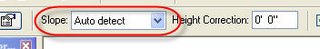
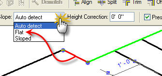
When working with stairs or railings there is a parameter associated with the sketch lines that define them. It is called SLOPE. There are three settings: AUTO DETECT, FLAT and SLOPED. Keep in mind that only the BOUNDARY sketch linetype has this parameter. The others are RUN and RISER, they don't. There is no special name for railing sketch lines, just called LINES. They also have the parameter.


Typically the setting 
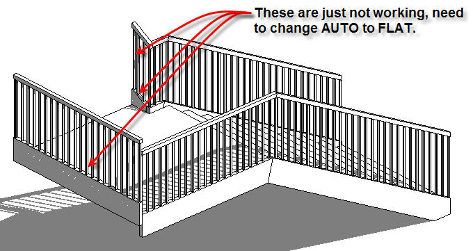
AUTO DETECT is sufficient. When you need to create stairs that are a little less than simple you will find these play a much larger role. Take a look at this image where we'd like to end the stair at the landing.

Now the trick to ending like this in the first place is to use a RISER not a BOUNDARY sketch line at the end.

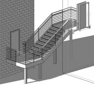
This stair has been told not to end with a riser yet the stringer at the inside corner is desperately trying to slope, and SUCCEEDING! Also the stringer at the far end of the landing and its railing are both too high. The stair and railing sketches just need a little SLOPE attitude adjustment.

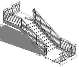
Setting them specifically to FLAT lets them behave. To apply this change you must be in SKETCH MODE to select each line segment. When one segment is selected you can alter the parameter. You cannot apply this change to multiple segments, it would be nice if we could.


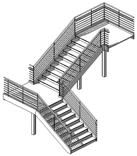
So this is the result!

I should also mention that when you make a stair Revit will automatically create a railing, if you let it. As long as you never edit the sketch of the railing Revit will keep track of it. As soon as you edit the sketch for the railing Revit hands over the responsibility for the integrity of the railing sketch to you, preferring to avoid making a change to it that you may not have wanted.

Till next time here's a few parting images! Cheers!


I recently recorded a VIDEO to describe this too. You can listen and sort of watch here.