Showing posts with label sketches. Show all posts

Saturday, April 13, 2013

Floor Perimeter

When you examine the properties of a floor you'll find Perimeter. Somebody decided perimeter shouldn't be available to tags so we can't tag a floor but we can see it in schedule (no, can't tag it in 2014 either).

If you alter a floor sketch to define an opening for something like for a stair or a mechanical chase, it alters the perimeter calculation. If you use either a Shaft Opening or Opening by Face it doesn't alter the perimeter value. Floor A is untouched, B is altered within the sketch and C has two openings one of each type. You'll see in the schedule that perimeter is not altered except where the floor sketch is changed to create the opening.


The moral of the story? If you'd like to be able to use the floor slab perimeter value then don't edit the floor sketch to create openings.

Tuesday, April 10, 2012

Finish and Cancel Inequity

In the past Aaron Maller and I have had long conversations that oddly enough focus on Revit. He mentioned the inconsistency between the way some elements that are sketch based are finished and the way shape editing for floors and roofs finish. He recently reminded me of it, for example he put forth this list.

Floor, roof, stair or ramp Sketch Creation = Finish and Cancel
Edit Profile = Finish and Cancel
Model Groups = Finish and Cancel

Floor or roof Shape Editing = Accidentally hitting the escape key and getting kicked out of it. We are supposed to click the Modify button to finish Shape Editing.

It would be great if Shape Editing were consistent with the others!!

Tuesday, January 03, 2012

Sorry You are Too Short

No I'm not picking on short people, that's Randy Newman's domain. Revit does have a bias against short lines (as most of us are well aware). Try sketching a line that's less than 1/32" long and you'll get this message.


It also doesn't care much for moving or copying elements very small distances. You may have run into this message?


What may not be obvious is that you can often trim a line to be shorter than the minimum size of 1/32". The threshold appears to be 1/128" (.16mm). In my experience this appears to work for most families such as annotation, detail component and generic model families. I've tried it in various project views including a drafting view without success. The project environment seems to be entirely intolerant of slipping past the 1/32" (0.780369mm) threshold. Trying to get smaller than that generates the first warning again.

If you want to copy/move something a smaller distance and get the warning, try dragging or using CTRL + Drag. You can get the arbitrary smaller distance and then use the temporary dimension to set the actual distance you want. Sometimes you can affect this limitation by zooming in closer, at least with regard to move or copy.

Fwiw, 1/128" converted to decimal is 0.00781250". I was able to make a line shorter still, to this decimal inch value 0.0063477", however Revit could not display anything other than 1/128" unless I changed the project units to decimal inches first using six decimal places. It is possible to create shorter lines than we are accustomed to (Revit limits) but only in family files.

Thursday, December 22, 2011

You've Got a Bad Profile

Considering the time of year and checking lists you don't want a bad profile. If you create a profile family for a railing and don't do a very good job of it Revit won't offer you your profile in the list of available profiles.


The missing profile you expect to find here is a clue that your profile is bad. You need to check your sketch to  make sure you don't have a Bad Sketch. Only kids with a good profile get to use their profile in their railings.

Tuesday, May 04, 2010

Dept. of Errors - Slightly Off Axis

David Duarte (Revit Beginners blog) mentioned in a post at AUGI that he's observed that detail lines in drafting views that are drawn at very small angles no longer generate warnings or are stored in the Revit Warnings dialog box. He posted at AUGI looking for confirmation that it is supposed to be working this way now or not. I don't recall it being mentioned at all in the various sessions regarding new features.

In my testing I find that Model Lines do generate a warning message and store a warning but Detail Lines do not when sketched in Drafting Views (or plan views for that matter). In the following image (in a regular floor plan view) the model line generates a warning but the same angle does not for the detail lines.


Hopefully this is an intentional change. Regardless it is welcome since I've seen many projects littered with such errors in drafting/detail views. In particular those that have been created from external cad data originally. Now they just need to reconsider the <1/32" (less than) line length limitation, at the very least in drafting views.

Friday, September 25, 2009

Are You a Good Sketch or a Bad Sketch? Part Deux

I wrote an article about this before but just put an image in the post. I thought I'd revisit it with a video this time. You can listen and watch here too.


Friday, September 04, 2009

Stair Sketches - A Flat Slope Update

I updated this old post with a short video to help explain the situation. If you'd rather just watch the video here now, here it is.


Sunday, March 29, 2009

Are you a Good Sketch or a Bad Sketch?

Aah sketch mode. What a picky feature! It wants nice clean perfect sketches. It is a pass/fail proposition, it works, it doesn't. I think of electrical circuits when I think of sketch mode, as in "open circuit" and "short circuit". I also think of tool paths for a CNC machine or the laser cutter/etcher you use for model making (some of you). I also think of Jeffrey McGrew and his Shopbot "Frank". Yes he named his machine. Anyway these devices like clean endpoint to endpoint sketches. A bad sketch means damaged work or in some cases even a small fire?

In yet another life of Mr. OpEd I worked for the theater equipment manufacturer J.R. Clancy and we had a sub-contractor that used a CNC machine to cut the side plates, out of steel, for the rigging loft and head blocks (pulley assemblies), among other things. They used to be fairly casual about who could create the drawing for them to use to cut these steel plates until someone sent one with a "Bad sketch". After the shop foreman and management apologized profusely for the trouble it caused only ONE person could do the job thereafter. No...thank goodness it wasn't me that caused the problem, I think?!?

Here's a graphic of good and bad sketches. Be a good sketcher, keep Revit happy!
It would be nice if Revit would fix bad sketches since it is smart enough to detect that a bad sketch exists! See? One of a few versions of this complaint.

It does however try to show us where the problem is and then waits for us to figure out how to resolve it. That's something I suppose.

Friday, January 30, 2009

Department of Quirky - Stair Sketch in Workset Projects Update

I posted THIS back in March of 2007. I was visiting an office recently and we were chatting about this issue and one of them said, "Oh I found a way to fix that situation!" I said, "I'm all ears!" (not literally...it's a figure of speech).

She said the key is to draw the boundary lines continuously, don't stop them at the top of a run and the beginning of the landing. In other words don't draw them from point to point along the sloping part of the sketch draw them from the bottom of the first riser up to the end of the landing and repeat for each side.

In the image above I show one of four sides that would need to be done this way. After you sketch in this way, use the Split Tool to split the boundaries into the required segments. The sketch will finish without complaint. Certainly easier than pasting into a stand-alone project file or building the stair in the stand-alone file.

This deserves to be in the Dept. of Strange but I don't want to start another whole department. I'll have to place an ad to get another reporter and Freddy has been so unreliable lately I just don't have the patience.

Wednesday, January 30, 2008

"Sketchy Grids"

One of the things that jumped out at me in the book that Eddie Krygiel, Greg Demchak & Tatjana Dzambazova wrote, Introducing Revit Architecture 2008 was an image where they used lines to exaggerate where the perimeter of the building was. It was a nice effect both in plan and 3D. I've attached a couple weak attempts to recreate it from memory. I'm sitting in a hotel without the book so...forgive me if I get it wrong. Check out the book if you haven't and don't forget they've finished the companion book Mastering Revit Architecture 2008.

Here's a plan view:


Here's the 3D view:


Not as sketchy as SketchUp but then my examples don't look as good as the book's examples. Probably because the design of their building is much better than my little quick "house". Check theirs out!

Wednesday, September 26, 2007

Sketch Lines and Visibility Graphics

You turned off all the model categories in your view using Visibility/Graphic Overrides, the easily remembered VV or VG keyboard shortcut. Now you create or edit an element defined by a sketch and no linework...hmmm. Sketch Lines are a model category and are affected by the "Lines" category so you can't turn off the "Lines" category without losing them too. They don't appear as an item in the list because Revit assumes that it doesn't make sense to turn them off. Too bad turning off the parent category results in the same thing. Maybe sketch lines need to divorce their parent?

Tuesday, July 31, 2007

Overlapping Lines - Review Warnings

You've just attempted to finish the sketch of a stair, floor, roof, ceiling etc. and you are staring at the dreaded "can't finish sketch". It might not be obvious but you can use the Tools menu > Review Warnings to track down the trouble maker(s). You can also pan the view with the scroll bars to make is easier to see the whole sketch as well as using the right click menu viewing options. This way you don't have to resort to the delete...undo...delete...undo...cycle to find the troublemaker(s).

Happy Reviewing...

Saturday, April 22, 2006

A Flat Slope?

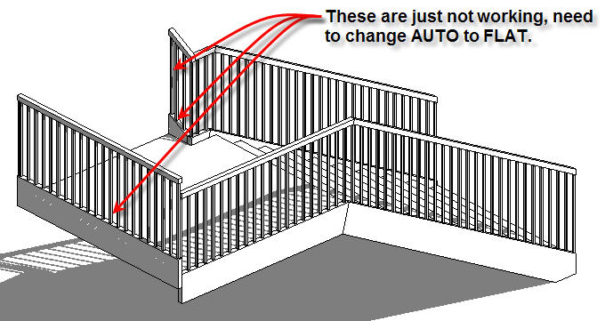
When working with stairs or railings there is a parameter associated with the sketch lines that define them. It is called SLOPE. There are three settings: AUTO DETECT, FLAT and SLOPED. Keep in mind that only the BOUNDARY sketch linetype has this parameter. The others are RUN and RISER, they don't. There is no special name for railing sketch lines, just called LINES. They also have the parameter.


Typically the setting AUTO DETECT is sufficient. When you need to create stairs that are a little less than simple you will find these play a much larger role. Take a look at this image where we'd like to end the stair at the landing.

Now the trick to ending like this in the first place is to use a RISER not a BOUNDARY sketch line at the end.

This stair has been told not to end with a riser yet the stringer at the inside corner is desperately trying to slope, and SUCCEEDING! Also the stringer at the far end of the landing and its railing are both too high. The stair and railing sketches just need a little SLOPE attitude adjustment.

Setting them specifically to FLAT lets them behave. To apply this change you must be in SKETCH MODE to select each line segment. When one segment is selected you can alter the parameter. You cannot apply this change to multiple segments, it would be nice if we could.


So this is the result!

I should also mention that when you make a stair Revit will automatically create a railing, if you let it. As long as you never edit the sketch of the railing Revit will keep track of it. As soon as you edit the sketch for the railing Revit hands over the responsibility for the integrity of the railing sketch to you, preferring to avoid making a change to it that you may not have wanted.

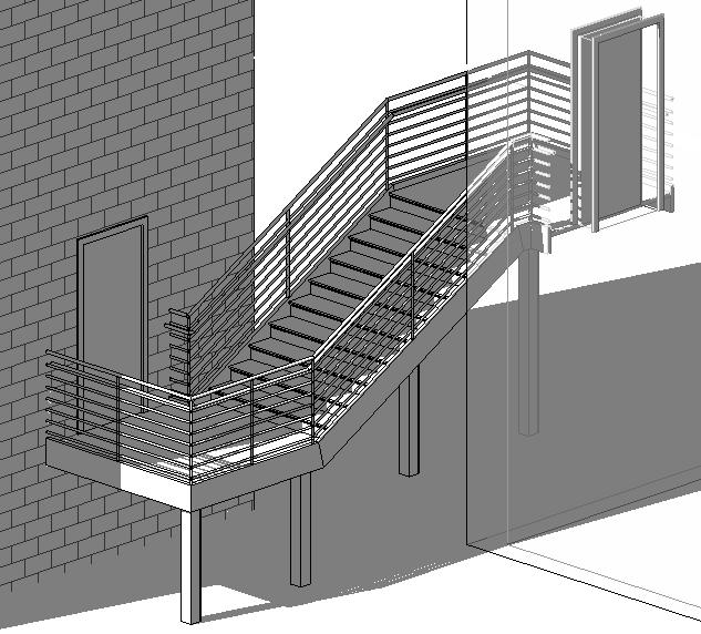
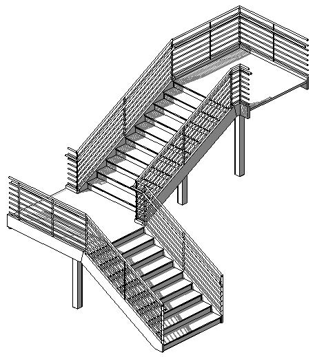
Till next time here's a few parting images! Cheers!


I recently recorded a VIDEO to describe this too. You can listen and sort of watch here.