Lately we've been experiencing some poor performance accessing BIM 360 projects. The primary cause eludes us at the moment, but Location Services, Windows Updates and Anti-Virus systems appear to be factors for now. Most of the time it works great but then...it doesn't.
Today I'm having trouble syncing changes with a project and this dialog has been stuck on my screen for about a half hour so far.
It's the fourth cycle of trying to Reload Latest... I think after a second failure to sync it should exit more elegantly. At this point I'm wondering how many times will it try before giving up? There is no option to quit or cancel...just stuck with forcefully quitting Revit at this point? That's polite.
Welcome to Steve Stafford's Blog ~ Revit OpEd = OPinion EDitorial ~ My view of things Revit, both real and imagined.
Tuesday, October 08, 2019
Tuesday, June 18, 2019
Eccentricity of Wall Footing
I replied to a thread at AUGI regarding the Eccentricity parameter of a Wall Footing. They observed that Revit seemed to ignore their input and didn't understand what it was meant to do. In this case the width of the footing was less than the value they entered.
The parameter is intended to shift the footing over, from interior to the exterior face of the wall. The footing starts out centered on the wall above.
The interior wall surface can be aligned (flush) with the interior face of the footing but not further, creating any overhang of the wall, which seems logical to me. A picture might help?
The parameter is intended to shift the footing over, from interior to the exterior face of the wall. The footing starts out centered on the wall above.
The maximum eccentricity is equal to (Footing Width/2)-(Wall Thickness/2).
The interior wall surface can be aligned (flush) with the interior face of the footing but not further, creating any overhang of the wall, which seems logical to me. A picture might help?
Labels:
Concepts,
Eccentricity,
Footing,
Parameters,
Settings,
Structure,
Walls
Monday, June 17, 2019
Reference Planes without Names
It is a common practice to add a name to the reference planes we create. If it isn't common where you work then it ought to be. The name helps give a hint to anyone that works in the model that this reference plane is more important than those without a name. It can also help understand what it is for, why it was made.
There are some who make the effort to clear out reference planes that are not named periodically, just another of any number of model/housekeeping chores. I've even seen Dynamo scripts intended for this task.
If you're using Ideate's Explorer you'll find it easy to see a summary of all the reference planes in the model. In the following image I've created two reference planes, one with a name and another without a name.
Notice that there are five (5) reference planes listed though. As it happens, when the Edit Profile concept is used on a wall four reference planes are created and internally applied against the sketch of the wall. They are only visible to us while editing the wall's profile sketch. We can't see these reference planes in the regular user interface, it only becomes very apparent with their Explorer tool.
It is also possible for us to create reference planes while creating any sketch based element, like a floor or stair for example. These reference planes are only visible to us while editing their related sketch.
The reference planes associated with a wall's edited profile can't be deleted via IDEATE Explorer. It can delete them when we've created our own within a wall's profile and other sketch based elements.
Attempting to clean up these unnamed reference planes might also be an issue if you're writing your own code or Dynamo script to delete them. We can/could add names to these internal reference planes (wall profile) but I don't think that's a task that worth the effort.
Something to keep in mind.
There are some who make the effort to clear out reference planes that are not named periodically, just another of any number of model/housekeeping chores. I've even seen Dynamo scripts intended for this task.
If you're using Ideate's Explorer you'll find it easy to see a summary of all the reference planes in the model. In the following image I've created two reference planes, one with a name and another without a name.
Notice that there are five (5) reference planes listed though. As it happens, when the Edit Profile concept is used on a wall four reference planes are created and internally applied against the sketch of the wall. They are only visible to us while editing the wall's profile sketch. We can't see these reference planes in the regular user interface, it only becomes very apparent with their Explorer tool.
It is also possible for us to create reference planes while creating any sketch based element, like a floor or stair for example. These reference planes are only visible to us while editing their related sketch.
The reference planes associated with a wall's edited profile can't be deleted via IDEATE Explorer. It can delete them when we've created our own within a wall's profile and other sketch based elements.
Attempting to clean up these unnamed reference planes might also be an issue if you're writing your own code or Dynamo script to delete them. We can/could add names to these internal reference planes (wall profile) but I don't think that's a task that worth the effort.
Something to keep in mind.
Thursday, May 23, 2019
Structural Column Disappears - Part Deux
Yesterday while trading messages with a friend we discussed my previous post about columns disappearing. He suspected it might explain the issue he was observing. After looking more closely it turned out that it doesn't. In his situation the structural columns were modeled the full height of the building and Join Geometry was used on walls, that passed through (overlapped) the columns, at each floor (level). The result: at some levels no column appeared while at others they do.
It was necessary to pull the walls back so they stop at the surface of the columns. Join Geometry allowed for the desired appearance and the columns reappeared at the other levels where they were missing earlier.
Wednesday, May 22, 2019
Filter Dialog and Reading a Long Filter Name
Dialog stretchiness has been an ongoing long standing user wish for all dialogs. Daniel wrote to me hoping that I'd echo his complaint about the Filter dialog. Yes you can stretch it but the frames remain less so. The Filter name frame does add a scroll bar at the bottom when a filter name exceeds the width of the frame, which does not increase in size when the overall host dialog stretches out. Ideally we'd be able to stretch/adjust individual sections of such dialog boxes. If memory serves that is dependent upon which GUI tools are being used to generate the dialog. If that tool set doesn't do it then...we don't get it...without a custom entity.
Daniel was writing about Revit 2019. Even when you scroll over to the right completely a filter with a long name gets truncated and you can't read all of the name.
I note that in Revit 2020 a tooltip will appear that displays the full name while the frame does the same truncating even when it has been scrolled completely to the right.
Naturally, we can avoid it if we can use Filter names that are not very long, an easy fix...there's that word again - easy. Easier said than done...it seems.
Daniel was writing about Revit 2019. Even when you scroll over to the right completely a filter with a long name gets truncated and you can't read all of the name.
I note that in Revit 2020 a tooltip will appear that displays the full name while the frame does the same truncating even when it has been scrolled completely to the right.
Naturally, we can avoid it if we can use Filter names that are not very long, an easy fix...there's that word again - easy. Easier said than done...it seems.
Labels:
Dept. of Wishes,
Dialogs,
Filters,
Graphic User Interface,
GUI,
Ideas,
Issues,
Long Names,
Names,
Naming,
UI
Monday, May 20, 2019
Structural Column Disappears in Detail View Type
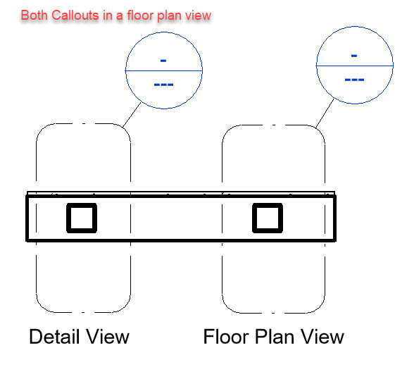
When we create a Callout within a plan view we can choose between Floor plan and Detail. A structural column that uses a negative offset won't show up when a wall exists in the same location when a Detail view type is used. It works fine in a Floor plan view type.
Here are some example images. The first one is showing the negative offset used. If the offset is zero then there is no graphical issue, the column shows up.
This image shows both callouts in the overall floor plan, Detail on the left and Floor on the right.
This is the Floor Plan Callout, column shows up as expected.
This is the Detail Callout, no column is visible.
This is the same Detail Callout but my cursor is hovering over the column and Revit sees it, highlights it despite not being visible. The wall is masking the column.
This is the same Detail Callout but the view is changed to use Wireframe and the column appears.
It boils down to the negative offset applied to the column. The graphics hierarchy does not respect the full height of the column and the wall element is drawn over the structural column. We can also get around the issue if we edit the column family and remove the option: Show family pre-cut in plan views.
Here are some example images. The first one is showing the negative offset used. If the offset is zero then there is no graphical issue, the column shows up.
This image shows both callouts in the overall floor plan, Detail on the left and Floor on the right.
This is the Floor Plan Callout, column shows up as expected.
This is the Detail Callout, no column is visible.
This is the same Detail Callout but my cursor is hovering over the column and Revit sees it, highlights it despite not being visible. The wall is masking the column.
This is the same Detail Callout but the view is changed to use Wireframe and the column appears.
It boils down to the negative offset applied to the column. The graphics hierarchy does not respect the full height of the column and the wall element is drawn over the structural column. We can also get around the issue if we edit the column family and remove the option: Show family pre-cut in plan views.
Wednesday, May 08, 2019
RevitForum.org Back
It appears to be restored via a new ISP and up and running again. Glad it's back!
...EDIT...some are saying it isn't fully set up at the new ISP yet...mileage may vary for a bit longer but it is on the way.
...EDIT...Site is still in transition to a new ISP, a message to that effect appears on the site until it is fully transitioned. (05/10/2019)
...EDIT...Site is UP, restored...aahhh
...EDIT...some are saying it isn't fully set up at the new ISP yet...mileage may vary for a bit longer but it is on the way.
...EDIT...Site is still in transition to a new ISP, a message to that effect appears on the site until it is fully transitioned. (05/10/2019)
...EDIT...Site is UP, restored...aahhh
Labels:
Forums,
Issues,
Posting,
RevitForum.org
Monday, May 06, 2019
Linked Details - 3rd Party Tool Options
This is an update to a much earlier post after getting a couple comments on that thread. These are three companies I'm familiar with that are providing solutions that contend with sharing details between projects and multiple model projects.
Revolution Design - Revit Workflow
26 Degrees Software - ViewAQC
Parallax Team - Parallax Linked Details
Check them out!
Revolution Design - Revit Workflow
26 Degrees Software - ViewAQC
Parallax Team - Parallax Linked Details
Check them out!
Tuesday, April 30, 2019
Revit Forum dot Org Not Working
It’s been about a week now where some of us can’t post/reply at the forum. I guess I’ll give up trying at this point. I can only spend so much time replying only to have the forum crash. Hopefully they’ll figure it out eventually. Maybe someone can tell me if/when that happens? Good luck!
Wednesday, April 24, 2019
Keynote Legends and Keynotes not Updating 2018.3
In Revit 2018.3.2.7 I am seeing and getting reports that keynote legends are not updating to show the current state of keynote tags visible in views. The existing workaround to force a refresh by turning on/off the Annotation Crop Boundary works but is entirely impractical to expect a team to open every sheet and do that task for each and every view on a sheet.
This past Knowledge Network post seems relevant. A portion of the text at that article suggests...
We really need this fixed ASAP!!
Workaround:
There are a few ways you could work around this behavior, and the best method will vary depending on the model geometry and number of affected tags. Here are a few options:
Temporary fixes (these will restore the display keynote tags, but future view changes will clear them again):
Temporarily adjust the location of the Cut Plane so that is above the affected elements (this will restore the value to the tags) and then restore the original cut plane location. Note: Some customers have noted that for views with dependent views, this process is required:
(Note: this may not work for some elements such as Duct; in that case, see the Non-temporary fix below.) Recreate the affected tags manually.
- Open the parent view and adjust the cut plane upward.
- open all sheets containing dependent views belonging to this parent view to refresh the keynote tags.
- move the cut plane back to its original position in the parent view.
Non-temporary fix (This will prevent future changes to the view from clearing the keynote tag): Adjust view or elements so that the cut plane is above the affected elements. (This could be done with a Plan Region.)
Labels:
bugs,
Complaints,
Issues,
Keynotes,
Legends,
Troubleshooting
Wednesday, November 28, 2018
Downloads Fixed - Some
I have been trying to carve out a little time here and there to fix the paths to downloads I've shared in the past. As of now the most requested stuff is fixed, the egress family and railing files. If you try to download something and hit a page not found warning, drop a comment in the post to bring it to my attention and I'll make it a priority.
Thanks for being patient - The mGmT...
Labels:
downloads,
Files,
Maintenance,
Sharing,
Troubleshooting,
Update
Wednesday, October 17, 2018
Reveal Elements - Hidden Viewport
The other day I was looking at a sheet a user reported it was impossible to select a floor plan view on. It seemed as though Revit did not see the view port on the sheet. People frequently pin views to make it a bit harder for other people to move them on a sheet accidentally. That will still allow a view port to be seen by Revit, it will still highlight as the cursor travels over it.
Then I thought of right-click Hide In View > Element. I used Reveal Elements and I could select the viewport. Using that tool does not hide what is visible in the view, it just disables the ability to select the view port.
Good? Bad? It isn't expected, well I didn't expect it.
Then I thought of right-click Hide In View > Element. I used Reveal Elements and I could select the viewport. Using that tool does not hide what is visible in the view, it just disables the ability to select the view port.
Good? Bad? It isn't expected, well I didn't expect it.
Monday, October 08, 2018
Change a System Parameter from Type to Instance - Not Length
It is fairly common knowledge that we can change a built-in parameter like Width from Type to Instance by going through the side door, selecting a dimension assigned to the parameter and changing it to Instance on the ribbon (see the image).
Kurt Thompson wrote to me to share how he gets around this issue when the parameter isn't something a dimension can be associated with. Specifically he was referring to a thread at the Autodesk User Forums where a member (electrical focus) was asking Autodesk to change the default parameters for Mains (instance), MCB Rating (type) and Subfeed Lugs (type). They argue that each parameter should be the opposite of the current configuration based on how the information is really dealt with (not that he needs me to, but I agree with him).
Kurt writes:
Kurt Thompson wrote to me to share how he gets around this issue when the parameter isn't something a dimension can be associated with. Specifically he was referring to a thread at the Autodesk User Forums where a member (electrical focus) was asking Autodesk to change the default parameters for Mains (instance), MCB Rating (type) and Subfeed Lugs (type). They argue that each parameter should be the opposite of the current configuration based on how the information is really dealt with (not that he needs me to, but I agree with him).
Kurt writes:
"To change a System Type parameter to Instance...(specific to the mentioned thread)Thanks Kurt!
Create a Shared Parameter built exactly like the built-in parameter you need to change but make it Instance instead of Type. Starting out with a Generic Model family, add the new parameter. Now assign the family to the category Electrical Equipment, Revit will replace the shared parameter with the built-in parameter but it will retain the Instance (or Type) property setting from the shared parameter. Give it a try."
Friday, September 28, 2018
Color Fill Calculation Failed is Back
This warning appeared quite a bit with Revit 2016 and patched in subsequent updates.

I've clicked Restart to no joy and I've submitted the error. I've done the Edit Color Scheme and Cancel process described for Revit 2016 with no joy either. Hopefully it will get sorted out again.

I've clicked Restart to no joy and I've submitted the error. I've done the Edit Color Scheme and Cancel process described for Revit 2016 with no joy either. Hopefully it will get sorted out again.
Labels:
bugs,
Calculations,
Color Fill,
Complaints,
Errors,
Issues,
Patch,
Troubleshooting,
Warnings
Thursday, September 27, 2018
Property Boundary and Coordinate Data - Dynamo
Alternate title: Mr. Revit OpEd finally does something (tho basic) with Dynamo!
I used this problem as an excuse to dig into Dynamo a bit. I created the attached graph to read a text file with coordinate values, one line per X,Y,Z values.
The text file format is very basic, it looks like this:
I created a 3D cylinder and model lines to form a target symbol family, 3D and fairly large so I could see it anywhere in the model. The graph places a target family at each coordinate location. Before running the graph, I assigned the Project Units for Length to Meter. Then I ran (manual) the Dynamo graph to place the target families. The last step was to start the Property Line tool and sketch the property boundary segments from target to target, which looks like this.
It was necessary to move the points closer to Revit's origin so they were not so far away, since Revit hates that. After doing that, I moved the Survey Point (not clipped) to one corner of the property (target family location) and then used Specify Coordinates at Point at that location using the coordinate values for that corner. This will allow me to export the result to DWG, if necessary. I also created a specific Spot Coordinate family type so I could identify some or every target location and make sure each reports the correct coordinates, double checking my work so to speak.
I probably spent a couple hours on this, mostly trying to get my head wrapped around which nodes in Dynamo to use. The next time I'll be twice as fast!
The text file format is very basic, it looks like this:
I created a 3D cylinder and model lines to form a target symbol family, 3D and fairly large so I could see it anywhere in the model. The graph places a target family at each coordinate location. Before running the graph, I assigned the Project Units for Length to Meter. Then I ran (manual) the Dynamo graph to place the target families. The last step was to start the Property Line tool and sketch the property boundary segments from target to target, which looks like this.
It was necessary to move the points closer to Revit's origin so they were not so far away, since Revit hates that. After doing that, I moved the Survey Point (not clipped) to one corner of the property (target family location) and then used Specify Coordinates at Point at that location using the coordinate values for that corner. This will allow me to export the result to DWG, if necessary. I also created a specific Spot Coordinate family type so I could identify some or every target location and make sure each reports the correct coordinates, double checking my work so to speak.
I probably spent a couple hours on this, mostly trying to get my head wrapped around which nodes in Dynamo to use. The next time I'll be twice as fast!
Wednesday, September 26, 2018
Links in Posts are Broken
An update to my company site has broken links to the files I've shared in posts throughout the history of my blog posts. Oh joy! I apologize for the inconvenience while I work through those to restore their paths.
Labels:
Blog Info,
Blog Posts,
downloads,
Info,
Status,
Troubleshooting,
Update,
URL
Thursday, September 20, 2018
Troubleshooting - Start an Email or Forum Post
I find it helpful to resolve an issue by starting to write an email or forum post (or a blog post) to ask for help or complain about it. Trying to write an explanation for what is happening so someone else might be able to help me focuses my thoughts. Very often I find it isn't necessary to finish writing.
The answer presents itself during the writing.
Next time you're puzzling over something, consider writing down what you think is wrong and the solution may arrive as you type.
Worth mentioning that a short break can also help a lot. Grab a beverage, talk to someone else, or stretch your legs; or all the above. The change gives you chance to work on the problem in the background of your attention.
Labels:
Advice,
Issues,
Problems,
Suggestions,
Support,
Tips,
Tricks,
Troubleshooting
Wednesday, September 19, 2018
Moving a Viewport Error - Disjoin
The Move tool offers us an option called Disjoin. When it is used Revit deletes the original and creates a new element at the new location. That isn't obvious to us but if you examine the GUID (ID's of Selection) you'll find it has a new GUID after the Move is complete.
The option is sticky, we have to remember to disable it when we use the Move tool again. When we are working on sheets and adjusting views we now have an opportunity to run into a confusing error message.
If you run into this or people you support do, just remember to Disable da Disjoin.
The option is sticky, we have to remember to disable it when we use the Move tool again. When we are working on sheets and adjusting views we now have an opportunity to run into a confusing error message.
If you run into this or people you support do, just remember to Disable da Disjoin.
Per a comment: My previous post on re Disjoin.
Friday, September 07, 2018
Post Echo - Units - Accuracy - Tolerance
I saw David Baldacchino's tweet yesterday sharing a link to a blog post for another software product called FME from Safe Software. The article goes into detail more related to their own product naturally but it does describe the math and computer problems that developers deal with. I found it quite interesting as well as confirming much of what I'd read and been told in the past.
Have a look! It's titled: "FME 2018 Infinity War: How Automatic Tolerance Defeats Infinite Precision without a Snap – but with Anchored Vertices!"
Wednesday, September 05, 2018
Wish - Release Type Catalogs after Loading a Family
Revit needs to release the Type Catalog files after loading a family that use them.
That message makes the process of updating a type catalog tedious at best if you have to close Revit completely to release it so it can be edited, very inefficient. There was a brief period of time when Revit did release the file as it should, but that ended with 2018 if I recall correctly.
Subscribe to:
Posts (Atom)