Friday, May 12, 2006

Dimension Parallel Arc Grid Lines

Ever wanted to do this?


Probably have tried and found that Revit won't? Some folks resort to adding little detail lines and dimension to those instead. This tip is brought to you by Kevin Parks, a hard working HOK Revit user in Dallas. He showed it to me the other day and I warned him that I'd have to share it! Thanks Kevin!

So start off like this...follow the "bouncing ball"...


Wrap it all up by adjusting the object offset so the witness lines finish up as desired. Refer to the first image for the final product. This works assuming the grid lines are parallel. Yep...works for walls too!

Sorry...no bouncing ball, just me trying to be amusing...

Thursday, May 11, 2006

Thumbnail Explorer Released into the Wild

Raizlabs has released Thumbnail Explorer. This is an interesting product, a graphical search engine for your PC and network, with interesting possibilities for viewing/finding Revit content not to mention other file types.

From the website:


  • Thumbnail Explorer is the perfect tool for anyone who deals with graphics, office files or CAD and has more then a handful of files.


  • The software allows you to quickly and easily find any file across multiple folders without browsing or using Windows search. As you type a part of file name Thumbnail Explorer will show a list of thumbnails and will enable you to work with corresponding files without resorting to Windows Explorer.


  • Search and thumbnail extraction done as background process that guarantees interactive responsiveness even when searching through hundreds of thousands of files.


  • The software features tight integration with Windows Explorer. Double click or drag and drop search results into their native applications. Or right click to see the same context menu as in Windows Explorer.


  • Customize our tabbed interface to your work environment and files


  • Easy to use interface requires no training


  • Do you recognize the name Raiz? Leonid Raiz is one of the two founders of Revit, Irwin Jungreis being the other. Leonid's son Gregory founded Raizlabs 1997. Leonid has been working, in his spare time, on Thumbnail Explorer since retiring from Autodesk about two and half years after selling Revit to Autodesk. He recently released it to a small beta group and is now pleased to release it to the general public as a Raizlabs product.

    Saturday, May 06, 2006

    Revit in Portugal x 2

    André Cardoso has joined Fernando in providing blog based Revit information. If you like or need your Revit data in Portuguese...now you've got yet another option! Be sure to check it out! His blog is called Up to Work. Happy reading!

    Walking on Thin Ice

    Another post about shared parameters. Here's the warning you'll find in a shared parameter file.
    If you've dabbled or dug in seriously with shared parameters you've most likely made a mistake naming or choosing the type for a parameter. The interface Revit provides doesn't allow you to change a parameter once you've entered the data and finished. The only route is to delete and redo....or is it?

    It is just a text file technically so you can open it with Windows application, Notepad. Best not to open it in Word or similar since you could inadvertently save formatting data in the file rendering it useless to Revit.

    Required Disclaimer: In light of the above image doing anything I suggest will not be supported by anyone if something goes wrong, you venture out on "Thin Ice" at your own peril. If you have used the shared parameter in a project and have data associated with it don't go here...walk away. You'll lose data. Scared yet? No...okay carry on...

    If you examine a shared parameter file, each value has a role.

    If you need to rename the parameter, rename it here >

    If you need to redefine the type, do it here >

    Keep in mind that you have to enter the type value exactly as Revit expects it to be written otherwise it isn't going to work.

    If you want to get a parameter from one file into another, just copy the entire string from one to the other.

    I don't know how many people will care about this or perhaps run away but during a discussion about this recently I tried it to fix something and found it helpful.

    This is only really useful if you are in the process of creating parameters and make a mistake. If you've already implemented a project or content using the parameters it may be more "costly" to change than it is worth. You be the judge.

    Wednesday, May 03, 2006

    New Build of Revit 9 Posted!

    Attention! New build has been posted. Build 20060426_2300 is now available at the Autodesk Revit Building web site. Start your downloading HERE NOW!

    P.S. This applies to Revit Structure 3 as well. Download it HERE!

    Saturday, April 29, 2006

    Cropped and Nowhere to Go!

    A subtle twist of the new Rooms in Revit Building 9 is that the tags for rooms will not show up when the crop region of a view does not intersect the room.

    If you recall in the past a room tag would linger off in space outside a crop region when you set up a partial plan etc. Then you'd have to delete those orphans. Now they just disappear from view automatically. The exception to this is irregular shaped rooms that still cross over the crop region's boundary.

    BEFORE CROPPING:

    AFTER CROPPING:

    Need an Excuse to go to Australia?

    Any Revit user/fan that needs an excuse to visit Australia now has a great one. To mix Revit and travel you just need to attend the Revit User Conference. It runs from October 26, 2006 through October 29, 2006. Check it out!!

    Here's a reprint of the schedule as it appears on the conference web site.

    Day 1 Thursday, October 26
    9:00am Setup
    1:00pm Introduction to Revit Building 9
    2:50pm Introduction to Revit Systems 1
    4:40pm Introduction to Revit Structure 3
    7:30pm BBQ - meet and greet

    Day 2 Friday, October 27
    7:00am Breakfast
    9:30am Welcome and Intro
    10:30am Morning Tea
    11:00am Keynote
    12:30pm Lunch
    1:30pm Modelling - Basics - Modelling - Advanced
    3:00pm Afternoon Tea
    3:30pm Families - Basics - Families - Advanced
    7:30pm Dinner

    Day 3 Saturday, October 28
    7:00am Breakfast
    9:00am Documentation - Basics -Documentation - Advanced
    10:30am Morning Tea
    11:00am Classroom 1 - Linking, Worksets, Shared co-ordinates
    Classroom 2 - Phasing, Massing
    Classroom 3 - Design Options, Scheduling, Workplanes
    12:30pm Lunch
    1:30pm Rendering - 3rd Party rendering
    3:00pm Afternoon Tea
    3:30pm Best Practices
    5:00pm Gala Dinner

    Day 4 Sunday, October 29
    7:00am Breakfast

    Tuesday, April 25, 2006

    Units Units Units! Unit Plans?

    Autodesk Revit is inquiring about unit plan requirements. What do we do? Why do we do it? They have posted a short survey to respond to. You can supply your comments at the end of the survey.

    Take the SURVEY if you care about UNIT PLANS!! Can you say improvements to Groups? Let's hope they come up with something great!

    Saturday, April 22, 2006

    A Flat Slope?

    When working with stairs or railings there is a parameter associated with the sketch lines that define them. It is called SLOPE. There are three settings: AUTO DETECT, FLAT and SLOPED. Keep in mind that only the BOUNDARY sketch linetype has this parameter. The others are RUN and RISER, they don't. There is no special name for railing sketch lines, just called LINES. They also have the parameter.


    Typically the setting AUTO DETECT is sufficient. When you need to create stairs that are a little less than simple you will find these play a much larger role. Take a look at this image where we'd like to end the stair at the landing.

    Now the trick to ending like this in the first place is to use a RISER not a BOUNDARY sketch line at the end.

    This stair has been told not to end with a riser yet the stringer at the inside corner is desperately trying to slope, and SUCCEEDING! Also the stringer at the far end of the landing and its railing are both too high. The stair and railing sketches just need a little SLOPE attitude adjustment.

    Setting them specifically to FLAT lets them behave. To apply this change you must be in SKETCH MODE to select each line segment. When one segment is selected you can alter the parameter. You cannot apply this change to multiple segments, it would be nice if we could.


    So this is the result!

    I should also mention that when you make a stair Revit will automatically create a railing, if you let it. As long as you never edit the sketch of the railing Revit will keep track of it. As soon as you edit the sketch for the railing Revit hands over the responsibility for the integrity of the railing sketch to you, preferring to avoid making a change to it that you may not have wanted.

    Till next time here's a few parting images! Cheers!


    I recently recorded a VIDEO to describe this too. You can listen and sort of watch here.


    Monday, April 17, 2006

    Revit on the Rocks!

    Rather...Revit Rocks!! Yet another Revit blog joins the fray. Daryl, the man who brings you DGCad and Revit tutorial videos has started a blog. Check it out!

    Friday, April 14, 2006

    Text Settings

    One thing I've always wondered about...why isn't there a Settings menu selection for Text Styles?? Nearly every other project setting does yet text doesn't...seems unfair to me.

    To manage text styles without this you have to either start the Text command or edit existing text objects to modify or create a new text style. I guess we don't have to make text styles very often? Is that the assumption perhaps? Still seems unfair!!

    If I were elected President I'd make sure Text gets a fair shake!!

    (that and fix the elevation TAG!)

    Thursday, April 13, 2006

    Workset Visibility in Linked Files

    We don't have discreet control over workset visibility in linked files on a view by view basis yet (not in RB9 either). We DO have the option to specify what worksets shall be linked in when we import the file initially, project wide mind you. When you use File > Import/Link > Rvt choose Specify.

    Revit will offer you the Workset dialog to choose which worksets to open or close.

    When we need to change these settings we have to use File > Manage Links > then choose Reload From

    Now specify which worksets you need again.

    Rooms in Revit Building 9

    One of the first things you may stumble a bit with Revit Building 9 is Rooms. They are now an actual element like a Wall, Door or Window, you place a Room and tag them. The tags no longer define a room. They are just like a door tag, displaying important information only.

    The Area Analysis tab on the design bar has become the Room and Area Tab.
    You'll find separate commands for Room and Room Tag under the Drafting menu. On the Basics design bar tab you'll find the Room command. The Room Tag command is found on the Drafting design bar tab.

    You can now tag a room in section views. You cannot place a room in section nor select it however. You CAN select a room in a schedule, then choose Show from the options bar now.

    There is a new Room Model Object category in Visibility/Graphic Overrides and three sub-categories. The Room category is off by default in section and elevation views.
    Color Fill governs the display of any color fill applied to the view. It doesn't affect the legend. Interior Fill turns on the system controlled light blue fill that you see when you are placing rooms, tagging or selecting them. Reference displays the crosshair and drag grip that you see when you place, tag or select Rooms.

    More about Rooms later. Be sure to take a look at the help topics for Rooms, they have been updated to describe their new behavior and features.

    Wednesday, April 12, 2006

    Revit Building 9 is Released and Shipping

    Finally!!! Revit Building 9 has been officially released to the Web and is now shipping to subscription customers. Download it HERE. The main site for Revit Building is HERE.

    Revit Structure 3 is also available for download now.

    In the near future we also will see the release of the brand new Revit Systems 1, stay tuned.

    Tuesday, April 11, 2006

    Revit Em Portugal?

    I've neglected to mention that there is a blog dedicated to those Revit users who speak Portuguese, Revit Em Portugal. Fernando hails from Leiria, Portugal and has been using Revit for quite some time now, perhaps longer than anyone in Portugal. He'd have to confirm that bit of speculation though. He started the blog in January and fortunately for me there are quite a few images to help me figure out what is going on. Yet another Revit blog to highlight my single language liability!

    In addition to the blog he is host to a user bulletin board community similar to those listed on my links sidebar. It is called RevitPT. If Portuguese is your native tongue or your favorite second/third language do check it out.

    Wednesday, April 05, 2006

    A Little Help From My Revit

    Okay...poor attempt to reuse a Beatles song title, or if you prefer Joe Cocker's cover of it...nevertheless here we go.

    When you are browsing the help documentation using the search function, have you ever wondered where the subject you are interested in is actually located?

    Next time you are using HELP (I need somebody!...sorry), check out the Index Tab

    Typing your query will usually yield nearly the same results as the Search Tab. When you double click on an offering in the list a dialog box is offered if there are sub-topics.

    After choosing the information to display, now click the Contents tab.

    Notice the table of contents has expanded to show exactly where your subject of choice is located? Makes it a bit easier to study related information as well?

    Have fun searching!

    Tuesday, April 04, 2006

    Automatic Sketch Dimensions

    Did you know these are lurking in every family that you build? As soon as you add a parameter to a dimension Revit starts using them. Take a look at this simple sketch, just a Model Line drawn over the vertical Reference Plane called Center(Left/Right).

    Nothing special to see eh? Just notice the direction of the line for later okay?

    Now take a look at the same family with a parameter added to the angular dimension between the Model Line and the horizontal Reference Plane.Never seen them you say? Well you have to know when to look! Or at least how to turn them on! They are off by default typically. When you are editing a family, click the View menu, choose Visibility/Graphics and click the Annotation Categories tab to see where they are hiding.

    So what are they doing? Revit uses them to infer intent once we start using parameters and labeled dimensions. If Revit does well, we get automatic behavior from our family with a minimum of effort. When it doesn't we get less predictable behavior. It is important to tell Revit what we want when this happens. Reviewing these Automatic Sketch Dimensions can help us decide what parameters we really need to add to eliminate any confusion.

    A short search of Revit's help documentation will yield a nice graphical example of how these work. Try here>>

    A subtle related issue is sketching lines directly on a Reference Plane. The first image showed the line drawn from the intersection of Reference Planes, up. This image shows the results of the parameter driven change.Reversing the direction of this line, drawing it from the top down toward the intersection yields better results perhaps?It is more reliable, or at least more predictable, to sketch lines, that are intended to be flexed with labeled angular dimension, away from Reference Planes entirely. Sketch them at an angle instead.

    Monday, April 03, 2006

    Revit Inside?

    Recently an architectural firm interested in finding a structural firm using Revit Structure asked if there is a resource to connect with such firms. My reply, I don't think so. I talked with my friendly neighborhood Autodesk sales rep and he said that there isn't such a "list" as far as he knows.

    So...I'm curious if anyone reading this might be interested in sharing such information so that other firms could find each other? I'm proposing that I could host a neutral web-based listing of firms that use one or more of the Revit applications. The list could be as simple as a firm name and web address or include more detailed information. A listed firm would be part of the Revit Inside list.

    I've reserved the web address REVIT INSIDE just in case there is interest in making such a list happen.

    Let me know via email address: staffordconsultingatcoxdotnet (replace the written at and dot accordingly)

    Thursday, March 30, 2006

    Who Wins? A Battle of Constraints

    Using multiple constraints Revit can find itself caught in the middle. As a result some constraints will take precedence over others. Objects that are aligned will override length constraints.

    If you apply both an alignment and length constraint Revit will complain that it cannot maintain both kinds of constraints. You can choose to remove the constraints. Revit will remove the length constraint and try to keep the alignment constraint.

    This image portrays windows that are aligned and locked to each other and the first window has a locked dimension to position it near the wall.

    Next we try to move the last window on the top right.

    ...and Revit complains...

    Choosing Remove Constraints...the result...

    Revit removes the length constraint and honors the alignment of the windows.

    Similarly, equality constraints lose to length constraints. Do both of these on elements and Revit will offer the same warning. When you choose to remove constraints Revit will try to keep the length constraint and remove the equality constraint.

    Wednesday, March 29, 2006

    Mastering Autodesk Revit Building

    Paul Aubin has been working hard on finishing his book about Revit Building and he is pleased to announce that it is done and nearly shipping. You can check Amazon for availability and check his site for more information.

    Well done! Another Revit resource for all the new Revit users to use!

    Hey...while I'm plugging a new book don't forget that Christopher Lay Fox and Jim Balding's book has been updated. Check it at Amazon.

    Tuesday, March 28, 2006

    Do you Revit in French?

    Then another Revit blog may come in handy? Daniel Hurtubise has started a blog and he's posting in French. He's the cadd manager for Lemay Michaud Architecture and they have offices in Quebec and Poland. He's also a frequent contributor to the Revit forums at AUGI.

    I can even make out the basic content of his article's even though I do not know the language. I guess enough Revitese is present to give me a clue? Check out his BLOG when you get a chance.

    Once Upon a Reference Plane

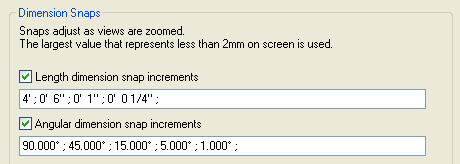
    [Updated to reflect current version options - 09/20/08]

    Once upon a time King Solid and his Voids prepared to journey across their great land, alas they weren't sure which vessel to use, Reference Planes or Reference Lines...abrupt end to segway...

    Reference Planes have slightly different roles when you are making a family versus working in a project.

    In a project they act as a construction line, a guide to layout your design. They do not have a real endpoint even though there is a grip at each end to adjust how much of the Reference Plane we see. Since there is no real endpoint you can’t snap to the midpoint of a Reference Plane. Just to confuse you though, you can snap to the endpoint of a Reference Plane, yes, the endpoint that doesn’t really exist.

    They have the same 3D/2D toggle that Grids and Levels have. This gives you global or view specific control over how much Reference Plane you want to see. When you don’t want to see any of it you can choose the Right Click option Hide in View > Elements (or Category if you want to hide them all).


    Change your mind later and want it back, click on the little light bulb on the View Control Shortcut Bar to turn on the Reveal Hidden Elements tool.


    Find the reference plane or planes you want to restore, select them and then click the Unhide Element button on the options bar or via Right Click.


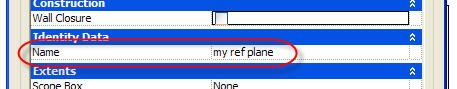
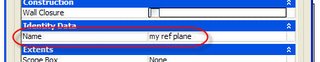
    Related to their role in families they can also provide a work plane for elements like roofs created with Roof by Extrusion, model lines, In-Place Families and Massing. To act as a workplane they must be named first, just edit its properties and supply a name.


    In the Family Editor their role is similar though with some additional responsibilities. Each Reference Plane has a parameter called IsReference. This is crucial to use properly so families behave themselves when exchanged for other families of the same category. It is also the key to making adjustable families that can be grip edited to change sizes when combined with instance parameters.

    The 3D/2D behavior of Reference Planes in a project does not extend to the family editor environment (not entirely true since Revit 2010). They are invisible in a project except for how the IsReference parameter permits them to be used.

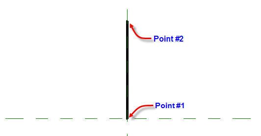
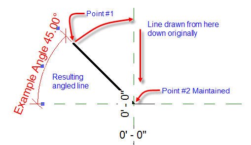
    In both a project and the Family Editor the orientation of a Reference Plane determines which direction is positive. Huh? When you create a solid or void on a named Reference Plane the direction or depth of that solid/void that is a positive value is derived by the orientation of the Reference Plane. Still confused? Okay here’s an image.


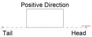
    When you sketch a Reference Plane the first point you place is the tail, the second the Head. When you name the Reference Plane the head is where the name appears. In the image above you should notice that the positive direction is to the left of the Head when the tail is “beneath” the Head. Try turning the image so the Head is at the top and the tail beneath (just try tipping your head to the right instead of trying to turn your monitor).

    The positive direction is always to the left of the head when oriented this way. Or is it? The existing Reference Planes in the stock Revit family templates behave exactly opposite. If you sketch your own they will abide by the rule above. Just these existing Reference Planes do not. I do not know why…hmmm.

    When you drag the grip endpoint of a Reference Plane across the other end, to flip the orientation, you’ll find that Revit will flip any objects that were using the Reference Plane.

    Reference Lines
    Since a Reference Plane has no real endpoint it can’t be relied upon to define angular constraints. In some cases you’ll get reliable behavior and you’ll flex a family and suddenly the angle seems to lose its bearings. Reference Lines were created to resolve this issue. So what about them, Reference Lines, that is?

    Well first of all, Reference Lines have real endpoints. This is important to maintain angular constraints. They have no counter part in the project environment except that they look and behave more like model lines (Revit 2010 has changed this a bit, update to follow) family editor. Despite this similarity they are a separate annotation category and the option to Hide Ref/work Planes when printing, within the family editor, controls their visibility as well as Reference Planes.

    They are associated with the workplane they were created on. This means you can add Reference Lines to the workplanes of other Reference Lines and/or Reference Planes allowing you to create complex nested relationships.

    Straight Reference Lines contain four work planes, one flat/parallel to the view/workplane the line is sketched in and the second vertical, perpendicular to the first, as pictured here.


    You’ll have to use the TAB key to select the second plane. These workplanes cannot be named nor can the Reference Line itself, you can only select them by using the Pick a Plane option when setting a work plane.

    Arc Reference Lines do not define any workplanes.

    Reference Lines only have three IsReference options, Not a Reference, Weak and Strong. Accordingly, they will behave the same as Reference Planes when loaded into a project. In the family editor, Reference Lines are also visible in a 3D view where Reference Planes are not.

    When you need to define workplanes that will flex according to angular constraints reliably, think Reference Lines. Possible uses for Reference Lines might be parametric trusses, 3D panel door swings or the “Pixar” articulated lamp example David Conant has posted at AUGI.


    When you place nested components or create solids/voids using the workplane of a Reference Line they will maintain their position according to their relationship to the Reference Line.

    And upon a Reference Plane/Line they lived happily ever after!

    Monday, March 27, 2006

    Where did he go?

    Who? You! Me? Yeah you!

    I'm sorry I've let the blog slide for so long this month. I could tell you how busy I've been, but that would seem like whining and I'm not because busy is great! Just sometimes busy means too busy to find enough to write another article. Fortunately other bloggers are keeping busy providing useful insight into Revit. So I may have been quiet but the information keeps flowing and I thank each of the others for that.

    So what is new? Revit Building 9, Revit Structure 3 and Revit Systems 1!! That's what!! The release of these new versions of Revit draws near!

    I attended three Revit user groups last week and saw presentations of each courtesy of Autodesk, LA CAD, South Coast Revit User Group, Inland Empire Revit User Group and LA Revit User Group.

    Amy Fietkau, an application specialist for Autodesk (also "Ask Amy"), presented the beta software and we were released from the quiet period on Thursday night at the last show. She did a fine job of showing/explaining and fielding the myriad questions thrown her way. I hope she got some rest over the weekend because not only did she do a whirlwind tour of three user groups but she also visited a bunch of area firms in between with Chuck Keeley, Southern California Autodesk Sales Representative. Almost rock stars! Just missing the tour bus and the deli trays, actually there was food...so just the bus then. Next time if you want a bus, let me know, I know some places you can contact from my old roadie days...

    The LA presentation drew the largest crowd of over 100 folks and John A. Martin & Associates provided the venue. The majority of those in attendance at each meeting were architects and primarily interested in Revit Building 9 with a few engineers in attendance in LA.

    So what can I say about the new software? Too much to mention in this brief post unfortunately.

    I can say the new room features are very nice. The ability of colums, in-place walls and curtain systems to be room bounding is great! Keynoting will be a very welcome addition for many. The very significant increase in control over the visibility of linked files is huge! Additional copy/monitor control for walls and slabs and additional API changes allowing creating views and sheets will be an asset too. Probably the biggest feature is the way we can save views from one project and use them in another. If you save a sheet view it will bring along all the related views on the sheet as well!!!

    One of my favorites that Revit Building inherits from Revit Structure is the improved options for sloping steel making it much simpler to slope steel under a warping roof surface.

    Revit Systems looks great! One feature, the creation of air flow analysis through a third party application like Trane Trace and the resulting color fill plan in Revit, drew the comment that it could save WEEKS in the engineering process alone.

    We do need to keep in mind that it is release one software. As such the focus has been on providing engineering data and not on completing the documentation of the design. Therefore, Revit Systems will be sold only as a bundle with Autodesk Building Systems until the documentation features are filled out more completely. The intended workflow is to only use Revit Systems if you are working with an architect using Revit Building. There is no intended workflow for using it with an architect using AutoCAD or other 2d/3d cad software at this time. I surmise that it is possible, just not intended...

    All for now!!

    Thursday, March 02, 2006

    Department of Subtle - Chain Option

    Sketching walls (or lines) every so often you want to sketch several sequentially and that is where the Chain option comes in.

    No surprises there really, expected actually. The thing I find to be subtle and elegant is that when I sketch a wall that touches another the command ends there. It doesn't try to continue sketching another segment from that intersection. It just makes sense to me. It is one of those things that you don't necessarily notice because it just happens and you can take it for granted.

    Subtle and elegant, NICE!

    Wednesday, March 01, 2006

    Active Workset

    Anyone who spends significant time in a project using Worksharing has put things in the wrong workset...maybe once at least? There really isn't a fool proof way to make sure that you always put them in the right place either, except somehow training yourself to always check it. I'm trying...really...

    So I had the pleasure of spending a couple hours with a pair of Revit afficionados in Minneapolis tonight. The first, Tom Dorner with Jafvert Mueller Architects and the proud owner of the blog Reviteer. The second, Rolly Stevens with Elness Swenson Graham Architects who I am embarrassed to say does not have a blog...YET! No worries Rolly...there are enough for now? I also met Dick Bates with Ryan Construction the night before. My thanks to Tom, Rolly and Dick for the chance to hang out with them while in town!

    Where am I going with this? Oh, yes...while chatting we ended up talking about Revit believe it or not and I was reminded of this idea I had see...what if?

    Let's say a scope box could be assigned a workset and any model object that landed inside could automatically belong to that workset? Well...after a couple of Newcastle's it seemed coherant. I'm sure something better is possible. This issue deserves some devoted thought since it remains one little chink in the armor of what is a really great feature of Revit.

    Again I'm one week too early to catch a local Revit user's meeting!!! Drat!

    Tuesday, February 28, 2006

    Nudge Nudge Wink Wink

    For Monty Python's Flying Circus fans this has an entirely different meaning than something Revit related...but it seemed so right...

    I'm referring to the Nudge feature in Revit of course. Even seasoned Revit users seem to forget how useful this is. Specifically this feature allows you to nudge a selected item or items instead of using the move command or dragging it/them to a new location. All by just pressing those trusty Arrow keys on your keyboard.

    Nudge isn't an arbitrary movement either. Based upon how much you are zoomed in or out Revit will use the Snap Increment to Nudge an exact distance. Revit will use a fraction of a snap unit when you change your zoom as well. If you wish to nudge a smaller or larger distance you can zoom in or out a bit. (see the default increments in the image)


    Using the Shift key and one of the Arrow keys will nudge 10x the nudge without shift, go fartherer more quickerer...

    So next time you need to tweak a piece of text, a viewport, a wall...well anything really...think Nudge Nudge Wink Wink??

    P.S. I've added clarifications to the above text on April 22, 2006 because both Leonid Raiz and Irwin Jungreis (Revit's founders) provide invaluable insight in posts at the AUGI forum.

    Friday, February 24, 2006

    New Revit Blogger

    David in Santa Barbara, CA has joined the blogging community. With articles starting in Janary this year, you can check out the tips and ideas he shares as he helps his firm implement Revit.

    David's Revit Beginners blog

    Tuesday, February 21, 2006

    Unpin Em All

    When you have a number of pinned objects you can unpin them one at a time using the little Push Pin icon that appears for the objects. The only trouble is clicking the pin only unpins the one you clicked. The others just get deselected.

    To unpin multiple objects you need to use the Modify ribbon/panel item Edit and choose Unpin. The default Revit keyboard shortcut for this is UP.

    Happy Unpinning!!

    Monday, February 20, 2006

    Irreconcilable Differences - Revisited

    As a follow up to the earlier issue I posted (Irreconcilable Differences). The inability to place these two types of objects using the Beam Command is limited to the command itself.

    As a workaround for now, and allowing you to use the intended structural categorized objects and structural template based families, just drag a new instance of the truss family into the Drawing Window from the Project Browser to bypass the Beam Command itself. I wish I thought of THAT!

    Thanks to Don Falkowski (Autodesk Revit Support) for chasing this one through and offering up a solution! It should be fixed in the next release, Thanks!

    Sunday, February 19, 2006

    Vizconnect, The Network!

    DISconnect the network to be specific.

    During a recent session the conversation turned to the excessive amount of time it takes to export a 3D view to dwg so the Revit model could be used in Autodesk Viz or Max. This prompted a little experiment. Set up a 3D view of a model, export to dwg, took several minutes to complete. Do the same thing but this time remove the network cable (from your PC) before running the export, took several SECONDS instead.

    Some anecdotal evidence suggests that having a network share of resources for Revit can contribute to this, such as the material libraries. As such the act of dis-connecting the network from the pc seems to resolve any such issue.

    When you need to do this for a project with Worksharing enabled you might also consider using Detach From Central to isolate the work you do from the actual project.

    This won't affect the export time but it will avoid having to Save To Central if you make any changes.

    Tuesday, February 07, 2006

    Phases, Views and Rooms

    Don’t change the phase of a view after you have put room tags in the view.

    Why?

    Rooms are Phase Aware, meaning they belong to the phase of a view they are placed within. Switching the phase of a view that has room tags means you’ll find yourself either losing the room tags or getting copies of them in the selected phase. In either case you get new rooms in the selected phase.

    If you ignore my warning, you’ll get an error message when you do that looks like this one. Don’t zip right past it without making sure you understand what will happen!
    Choosing Don’t Copy Tags means that Revit will create new rooms in the phase selected but not attempt to place tags for them. The rooms that were already there (tagged) remain in the project but their tags are deleted.

    Choosing OK means Revit will create new rooms AND create tags in the same location as the originals but in the phase selected. If no valid boundaries are found in this phase you’ll get the new tags but they'll complain they are Not Enclosed. Like the other option the previous rooms also remain in the project but their tags are deleted.

    My advice? If you need to switch back and forth between phases make sure you set up views assigned to these phases first.

    Still with me? Try a little example:

  • Start a new project using the default.rte Revit template
  • Open Floor Plan View: Level 1
  • Create four walls to form a single room, any size
  • Place a room tag
  • Create a room schedule
  • Set Phase to New Construction
  • Use fields: Room Name/Number/Area
  • Create another room schedule
  • Set Phase to Existing
  • Use fields: Room Name/Number/Area
  • Open Floor Plan View: Level 1
  • Tile the three views


  • Switch the phase of the view to Existing
  • Respond to the error/warning message with Don’t Copy Tags
  • Check results in view and schedules


  • UNDO
  • Switch the phase of the view to Existing again
  • Respond to Error/Warning with OK
  • Check results in View and Schedule


  • In either case you end up with rooms in both phases and you may not be aware of them since schedules show specific phases and by default when you create a schedule it uses the last phase in the list, so if you create a schedule and nothing shows up in it, check the phase!

    Can I Trust You?

    A common path for new Revit users is to import a dwg file and start tracing a project that got started in AutoCAD. Revit has a number of features that make this pretty easy to do. But just because it was drawn once in cad doesn't make it perfect or correct. I can't remember the last time I used a dwg file that didn't introduce some sort of error into the project I was involved in. What sort of errors am I talking about?

    The old they sure look lined up but they aren't problem for one. This one happens alot. Two lines that are on either side of a corridor, forming an opening look lined up but if you look closely you'll find that they are off by a tenth of an inch or less. So when you use the PICK option to place walls you get two segments that are off slightly. The ALIGN command will fix it quick but you'd have to notice it first.

    A sure fire hint that there is something wrong is when Revit doesn't offer a snap. If you pick an endpoint of a dwg line segment, move your cursor up to the other end and no SNAP icon is offered, BEWARE! The line segment is not aligned with the previous point.

    Another is the line is almost nearly exactly plumb or horizontal, or almost exactly a clean angular value. Such as 89.001 degrees or .003 degrees. Sketching a Revit wall or line over such a dwg source will generate an error message like this one.
    This simply means, "Gosh, this line is so close to a nice angle we thought we'd let you know that it doesn't make sense!"

    So the next time you start tracing a dwg file to start your Revit model, be a little skeptical and cynical about the dwg source, even if you did the work yourself. Been there, done that!

    Happy Tracing!!

    Friday, February 03, 2006

    A Little Flattery

    I read an article today about Tatjana Dzambazova, Autodesk Revit Building Product Manager. She impressed me the first time I met her with her energy and commitment to making Revit great! I hope you enjoy the article too! Oh...the article fails to mention that she only speaks seven languages, please don't hold that against her!

    Read THE ARTICLE

    By the way, we can help her do her job even better, as well as the rest of the team, by consistently logging our requests and support issues with Revit Support. She'll thank you for it! And you'll see the results in subsequent releases and builds!

    View Range and Floors

    I felt compelled to share a portion of a post in a recent thread (link below) from the Revit Forums at AUGI. Aaron Rumple, an Architect in St. Louis, Missouri and long time Revit user/supporter, provided the following insight about view range and how floors are treated or affected. See if you find it as interesting as I think you might? Keep in mind, this is part of one of several posts replying to a series of questions...

    Aaron wrote: It (a floor) shows in the Level 1 view because of a little known rule. Some objects show up when slightly below a level. This is the case of your floor. Floors will show up when they are below a bottom range from 0 to -4'.

    At -4' and below they then vanish. Yes, this is poorly documented and confusing. The original intent was to automate as much of the view setup as possible so that you wouldn't have to configure a ton of visibility settings. This works fine as long as a floor is a floor and not a footing.

    Typically, we would want floors of levels that step slightly to all show up in the same view as in the case of a sunken living space set down just a couple of steps. So Revit in its effort to speed the process can make things confusing when we use object in "non-standard" ways.


    I think this is a perfect example of why the Revit Community at AUGI is so great. Great questions and great contributions by the membership. Thanks to Aaron for the info!

    Here's a link to the recent thread. Keep in mind you should be logged into AUGI already to get to the post the quickest, otherwise, most likely you'll need to log in after clicking the link.

    New Revit 8.1 Build Posted

    The latest build (20060124_2200) for Autodesk Revit Building 8.1 was posted today. In her post at AUGI, Tatjana Dzambazova (Autodesk Revit Building Product Manager), wrote:

    The new build is primarily a service for the localized versions of Revit Building 8.1. There is one additional issue that has been resolved for the benefit of all users; the problem that the wall join on one end of a wall changes when the other end of the same wall is edited.

    You can download this latest build Build 20060124_2200