Thursday, November 17, 2005

A Roof: Massing an Octagonal Blend

A recent post in the Autodesk hosted Revit newsgroups asked how to make a roof form that starts with an exaggerated octagonal shape and rises to meet a uniform octagon, like this:
You are going to have to scroll quite a bit for this article, sorry…but images really help describe things right?

I thought I’d illustrate the steps to do this using Massing and a Solid Blend. All you really must "know" to model this is three things (beside how to use Revit), the shape of bottom, the shape of top and the overall height of the form.

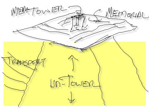
First you need a building concept so in this instance the following image is the first floor plan of the building.
This is the plan of the clerestory feature that starts on Level 3.
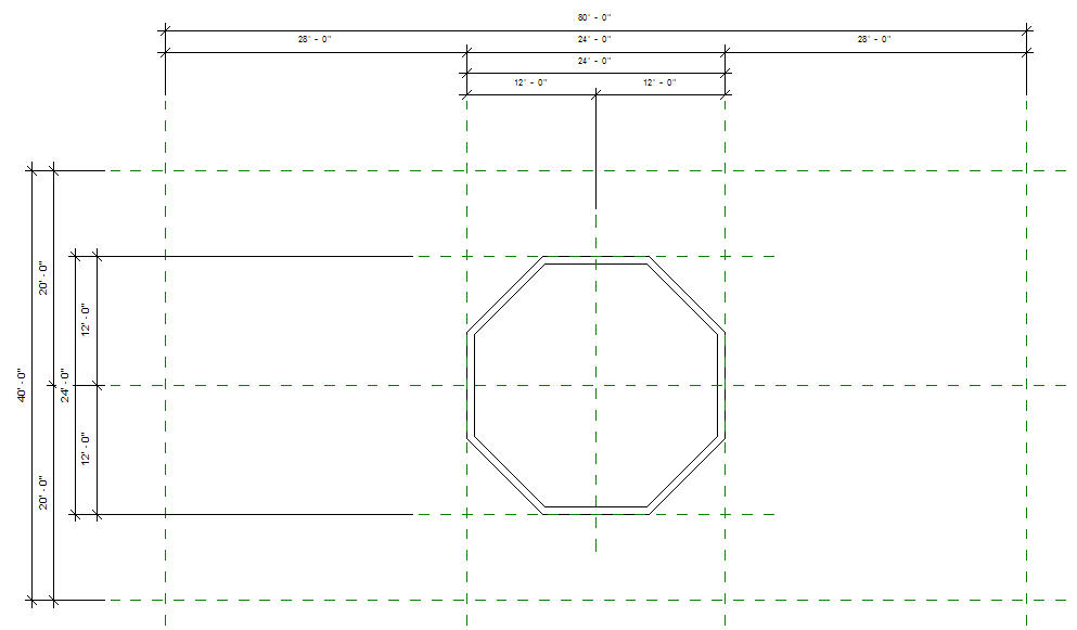
Here’s the South Elevation
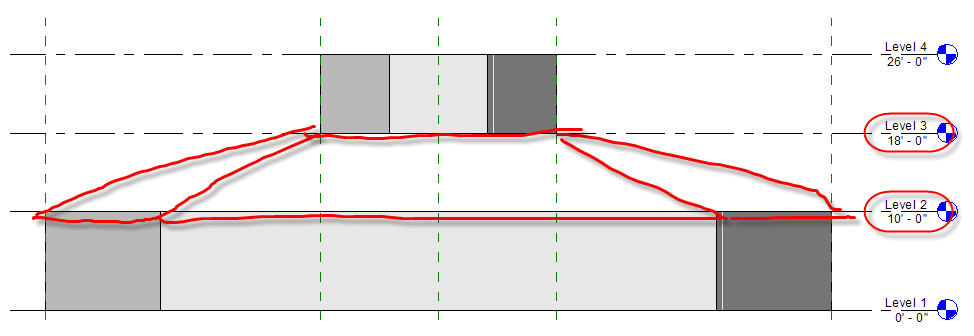
To start this off we need to click the Massing Design Bar tab, if it isn’t there just right click over the design bar somewhere and check the Massing option.
You’ll probably get this message if you haven’t been using Massing and created something already in this session of Revit. It’s just warning you that in order to create a mass family you need to turn on massing and Revit just did it for you, how nice!
Don’t know how to turn on massing? Here’s the button on the toolbar to toggle massing on/off. By the way, Revit doesn't show massing when you first open a project so don't panic when you do this for the first time and all your hard work is "gone"...just turn it on...she'll be right!
So let’s make a massing family (In-Place Family by the way)
Revit will ask you for a name for the family and offer Mass 1. You can accept it or pick a better name. Next Click: Lines and on the Options Bar choose, Polygon, enter 8 sides and choose Circumscribed Polygon
It really doesn’t matter how you sketch the base of the roof mass, use whatever method you like. Just keep in mind it must be a closed sketch and that you are sketching the base of the blend right now…the bottom or lower roof eave. Here’s what it should look like.Next we need to sketch the shape of the top of the roof. Click Edit Top on the design bar and you’ll see the sketch you just did is gray but still visible. Use the same procedure to sketch the upper portion of the roof like the image below.
Now click Finish Sketch on the design bar to finish the blend. Switch to the south elevation and you should see something like this.
In my case the depth setting was 20 ft so it is much taller than I wanted. I can just drag the upper grip after selecting the solid to pull it down to Level 3. I can also just enter the correct depth value on the options bar. Either way it needs to stop at Level 3.
Time to click Finish Mass on the design bar. Now we are ready to apply the roof. Choose Roof by Face from the Options Bar and pick the faces of the mass family. You may need to pick just the faces that follow the orthogonal walls first.
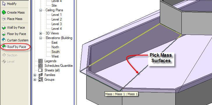
Depending upon the thickness of the roof you are using Revit may complain that it can’t finish the roof if you pick all the faces in one go. You can try it…or just pick the first four like in this image.
Click Create Roof

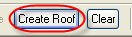
Now you are ready to pick the other faces.
Click Create Roof

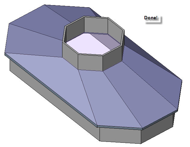
Changes made to the massing will permit you to apply those changes to the roof by choosing Remake on the Options Bar.This will only be available if the mass family changed and only if you pick the roof object afterward.
Happy Blending!

Wednesday, November 16, 2005

Moving Down the Street

Little morsel...Revit won't let you enter a value greater than 3000 ft (or 914400mm) when moving or copying an object for example.

Revit won't object if you pick two points that happen to be further than this though. Hopefully you won't really need to move something down the street this far but if you do, you'll be ready.

Why do I know this? I encountered a file that had civil data positioned 2.6 million feet from the original drawing area of the Revit project file. So moving this in increments of 3000 feet was going to take quite awhile, 867 times give or take a repeating decimal. So I thought, hmmm...what if I just pick two points? Happily Revit just moved the stuff over 500 miles for me in one go! Hooray!

Monday, November 14, 2005

Master of My Domain

For any Seinfeld show fans...the title will be "amusing". I apologize to those who aren't familiar with the show. What's my point? Glad you asked? RevitOpEd now has its own domain.

www.revitoped.com

For now the blog will remain parked right where it is and the domain is just redirected here. Hopefully it will be even easier to find.

A second domain www.stafford-consulting.com is also reserved and waiting for me to have time to put something together.

Cheers!!

Friday, November 11, 2005

de-Value Engineering Dimensions

We can’t override dimension values in Revit, by design. Nevertheless we covet the ability to do so. The images below are a few examples of what I consider legitimate reasons to be able to do this. Information that looks like dimensions but conveys different data than conventional linear, angular or radial values.


So how did I do all of these in Revit? I used a font that has been stripped of all the symbols it had, rendering it blank. Placing a dimension that uses this font means there is no value, nothing, nada…to see. Then I just placed some text above the dimension line.

Ouch!! A cursed workaround no doubt! But in the end it is what we need, something that sure looks like a dimension but isn’t. Or is it? Of course it is still a dimension. Picking the object the dimension is referencing will still allow you to change the objects position by clicking on the blank field to enter a new value.

Another way to do this is to setup a dimension style that uses a much smaller text size so it is easily hidden by the text you place over the top.

Remember that each dimension style can use its own rounding and formatting rules or the project settings. By default they use the project settings. The dimensions for the cabinetry above that show just inches are an example of such an override.

Here’s a bit of the OP part of OPED…

On several occasions I’ve suggested that Revit simply provide us with a tool that places annotation that happens to look like dimensions. It does not manipulate geometry as real dimensions do yet could adjust to reflect changes in geometry so the annotation remains aligned with the references that were picked originally. The information displayed would be entirely up to us. In fact nothing would appear unless we did enter something.

That said, this is a bit of a “slippery slope” since a user could dimension a project with this tool instead of with real dimensions and create a potentially horrendous situation both from a liability and workflow view. Simplistically we can blame that on training, but we are responsible for the situation since we’ve asked for it, invited it even.

What are we after when we say we need to override a dimension value? Well, some are suggesting that we should be able to type in whatever we please. I prefer that this not happen. The trustworthiness of information is all we have. If the information isn’t trustworthy, we won’t trust it, use it or profit by it.

When we tout the virtues of building information modeling yet argue to undo the inherent integrity that Revit offers we risk chopping off our own fingers!

An example of this is the Reference Other View feature.

We all clamored for this, argued passionately for it and then got it and now wouldn’t give it up. Yet, what happened as a result is the inherent integrity of no view being incorrectly identified was compromised. No longer can we look at the detail bubble and know with confidence that the detail we find is the one we wanted to show within our set of documents. Sure, there will be a detail exactly where we said it would be, but it might not be the right detail because I picked the wrong one from the list. At least true for symbols that carry the mark SIM, OPP or TYP, assuming we make sure to use them. If we don’t, then all bets are off.

Sometimes we need to be careful what we ask for.

Thursday, November 10, 2005

Make Up My Mind

Toggle Several Parameters At One Time

With Revit’s Yes/No parameter data type it is very easy to toggle two parameters using the statement: Not(Option A) in the formula field for Option B. Un-checking Option A checks Option B automatically. Checking Option A un-checks Option B automatically too.

It isn’t so straightforward to apply the same concept to multiple check boxes. Let’s say we’d like to have four options and only one of them should be visible at a time. These objects require their own yes/no parameter to make them visible or not. To decide which option is visible we’d like to just check the option we want and see the others unchecked automatically.

Here’s one way you could accomplish this. Let’s say we have one parameter using the integer data type, called Choose Option. We also have Option 1,2,3 and 4 parameters (yes/no data type) to assign to the objects involved. If we just add a formula to each option parameter that determines whether it is yes/no we can toggle our choice very quickly, with one data entry.

Is it almost as quick as checking a box? Pretty close!

One little side effect, if you enter a value that doesn't have a corresponding option...nothing is visible and you turn off all options! Good, bad? You be the judge.

Thursday, November 03, 2005

Matrix Schedules

Every so often someone asks if they can create a schedule that uses dots for a “yes” and a blank for a “no”. These are typically used to indicate, "yes we want a particular option" versus "no we don’t". A door schedule might use it for a Electric Hold Open or Automatic Door Closer and cabinets might use it to indicate Lockable Doors. No shortage of possibilites.

The answer to this question is a qualified “no”. You can’t choose a “dot” format for yes/no data. Revit only offers Yes/No. It certainly isn’t difficult to understand what Yes/No means when you read it, but people still prefer the graphic nature of a simple dot.

This is a long way round to say you can still do it eh? How? Using the Character Map application we mentioned in an earlier post Are You A Special Character? Some fonts have a dot symbol and Times New Roman just happens to have a pretty nice one. There are a couple others like Century Gothic and Garamond but theirs are little wimpy compared to Times New Roman’s. Here’s the character map info for Times New Roman’s dot symbol.

So how do you set this up? Easy really, you just need to add the parameters that you require to a schedule, using the data type “Text” instead of Yes/No. Then in the field(s) of the schedule enter the symbol value instead of text. Don’t enter anything when the answer is no. Refer to the earlier post for more detail on capturing the symbol value and entering it. Here’s a simple little schedule as an example.

News at 9:48


!!The un-Tower Project!!

Reacting to increasing political pressure to make the Freedom Tower project safer from potential future terrorist attacks, the principal planners and designers have changed the scope of the project again! No longer will this project be one of the world’s tallest buildings, it will be the worlds deepest!

Instead of going up, the tower will now become the un-Tower, a deep subterranean structure. The above ground site will become a memorial and little hint of the major structure below will be visible.

Anticipating the likely concern about natural lighting and fresh air, the designers have created labyrinthian chases to refract/reflect light from the surface into the deep spaces below. All habitable spaces will have extensive arrays of LCD panel displays to simulate natural lighting and will have higher than typical ceilings to enhance the feeling of space.

Fresh air will be pumped in from Connecticut and New Jersey. Rutgers University specialists are consulting with the designers to create special filtering equipment to make the air elegant and fresher than fresh. Responsible for a study linking scent to the enhancement of retail sales and the shopping experience, they hope to prove that this can extend to the work environment.

The planned and existing expansive undergound network of transportation will be extended to provide direct service, door to door, to many of the earliest committed tenants thus reducing the load of surface transportation to get staff to the site and to their offices. The structure will require additional reinforcing and multiple bulkhead water barriers to keep the water’s of the Hudson River and East River out of the structure. There was some discussion about creating a large aquarium viewing structure on the East River side but it was decided there isn't really much to look at there and certainly visibility wouldn't be very good.

No longer limited to just the width of a tower the project will be able to nearly double the original leaseable space. The deeper the building goes it will taper outward and increase the interior space available, an undergound elongated pyramid. The following image is from a crumpled sketch found by this Author before being escorted from the building.


When this new plan will be officially unveiled is not known at this time. Attempts to confirm this story by speaking with city and state officials were unsuccesful, not really surprising to this Author.

About the Author: Freddy Latherdon has been undercover for the last two months in the Wall Street section of New York City working in the copy room of a prominent architectural firm. His cover was so effective that he managed to acquire the nicknames "LOOser" and "THE copy GUY". In fact his inept attempts to actually do the work expected of him resulted in this story. Accidently seeing the memorandum describing the planning for this project he realized that his efforts were rewarded and now had the makings of a great scoop. Thanks Freddy, you heard it here FIRST! This more than makes up for you getting fired!

(Fiction, more fiction, utter fiction…do not be mislead…it is fiction…yep, not a word is true!!)

Monday, October 31, 2005

Ignore Good Advice

I've written a number of articles about parameters now and I’ve made the “blanket” statement at least twice now, “Don’t put shared parameters in a family unless you are changing geometry.” While this is accurate there is a reason to ignore this advice. And that is, when you create content apart from an actual project environment.

My advice has been from the myopic viewpoint of an architectural firm working through a project and building their own content. They know what they want or need to schedule and build accordingly.

What if you make content for other people like a window manfacturer or playground equipment manufacturer? What if you want parameters that are specific to the products that you're building content for? What if the stock system parameters don’t suffice? Shared parameters to the rescue!

When you use one to establish the information in your family the user will inherit the information when they load it into a project automatically. Better yet they’ll be able to schedule it even though they don’t have the shared parameter file you used to create it. They won’t be able to put that information in a tag unless you provide them with one too, which is a pretty a good idea.

Now switch sides…do you (the user of this nice family) want to add that parameter to your shared parameter file? Yes? Perfect! Playing along nicely!

There are two ways to get to this shared parameter, the family or in a schedule. Either way you need to be able to “touch” the parameter so you can use the Export option for shared parameters. Revit will add the parameter to the current shared parameter file you are using.

In a family you need to open Family Types, select the parameter, choose the Modify button.

In a project schedule you need to take a look at the view properties for the schedule, view the fields, pick the parameter, then click Edit.

In either case you just need to click Export and Revit will warn you that it will add it to the current shared parameter file you have. If Export is not active you don’t have a shared parameter file selected yet. You’ll need to do so first. Use menu item File > Shared Parameter to browse to find it or create one from scratch.

The only family type that doesn't play along with this scenario is titleblocks. Shared parameters that are used in titleblocks must be "connected" to a project by adding the shared parameter to the project as a project parameter, since titleblocks are sort of a "tag" for views.

Sunday, October 30, 2005

Seeing Backwards

When is a front elevation really a back elevation? When you are using a generic model family template. When you open a door family template the elevations behave “normally”…meaning the elevation of the door is as if you are standing in front of it and looking at the door.

When you take a look at the generic model template the view is as if you are standing behind the “door”. Since there is no “wall” you can see everything.


I suppose this could be partly because there is no host? Nah, more likely it is just the elevations are named backwards. Not as obvious since there isn’t any real sense of Exterior/Interior with a generic family. If you treat the "bottom" of a plan view as "front" and the "top" as "back" the views are named correctly. This just happens to be the opposite of how hosted families are setup. It isn't consistent and that can lead to confusion eh?

As such, the wall based family templates have “normal” elevations while the other templates do not.

Saturday, October 29, 2005

Shared Parameters - Part 4

Time flies...It is well past time to connect the shared parameter to the door family. Just to refresh our memory, the only reason we need to used a shared parameter in a family is when it will change geometry. Otherwise a project parameter (based on a shared parameter or not) is a more efficient way to propagate a parameter to all objects of a category.

We will:
  • Add Reference Plane to a door family
  • Align and Lock the door panel solid to this plane
  • Add a dimension
  • Add a label (using the shared parameter)
Let’s do it:

  • Open the stock door family Single Flush.rfa
  • Open Elevation View: Front
  • Sketch a new Reference Plane two inches (50mm) above the Reference Level
  • Select the panel geometry, choose Edit (to edit the sketch)
  • Align the bottom sketch line to the new Reference Plane, Click the Padlock
  • Finish sketch
  • Add a Dimension between the new Reference Plane and the Reference Level
  • Select the dimension, Add a Label


  • Click Radio Button: Shared Parameter


  • Choose Group: Doors and Parameter: Undercut


  • Click: OK
  • Group: Dimensions


  • Click: OK
Should look something like this now!


Now when this door is loaded into a project Revit brings along the parameter, it will appear in the type parameters for the door and can be scheduled, no more effort required.
Done!

Thursday, October 27, 2005

The ol' Edit Type then Instance gotcha!

(Edited: 12/30/05 - New build of 8.1 20051214_2200 fixes this bug)

A little nasty bug lurks waiting to nip at you. If you edit a family's properties by first changing a type parameter and then immediately change an instance parameter. Revit will give you this unpleasant message.

Give an example? Okay, take a door family, you add an instance parameter. It doesn't even have to do anything, it can be text or length...doesn't matter. What matters is, in a project, that you change a type parameter and then change an instance parameter in the same property editing session. It only affects instance parameters that you add to the family, not those that are built in.

Fortunately the fix is like going to the doctor, telling him/her that it hurts when I do "this". They reply, "Don't do that!" If you change one or the other, close the editing session and then edit the family a second time, all is well.

Seems to affect hosted families as opposed to furniture for example. I was able to reproduce it in doors and windows but not a desk.

Yes this is true for the latest build (8.1 - 20051017_2000) as well. I've reproduced it as early as release 7.0. I don't have earlier versions installed to test, not that it really matters at this point.

Tuesday, October 25, 2005

New Revit Blogs!

A couple new blogs started by Revit users in South Africa! They are:

Family Man and Revit Implementation

The first has several posts already while the second didn't have one yet. Be sure to check them out!

Saturday, October 22, 2005

Revit Can Coach Soccer

Not your typical Revit tip…

So I was thrust into coaching my son's U-10 boy's soccer team last weekend. We’re still looking for our first season win. A bunch of really nice kids that just can’t catch a break so far. So I needed to do a little planning for the positions each would play. So what did I do?

Did I use a pencil and paper? Started to but then I thought, hmmm...

If I use Revit I could pretend a room was a player/position and using phases I could simulate the quarters they play. The end result used the same collection of "rooms" (players) and I assigned them to different locations on the "field". I made it easier to see all the quarters at one time because I put four views, each quarter/phase, on sheet. Then I put all the players (room tags) on the sidelines and dragged them into a position, for each quarter. With this age group, AYSO doesn't want a player to sit out for more than one quarter of a game. That's the tricky part and what I struggled with using paper and pencil.


Bizarre? Yes! Did it work? Very nicely!! Revit is clearly becoming as important in my household as duct tape. Hmmm, I wonder how I could use it to change the brake pads on the car?

Monday, October 17, 2005

Wiki See Wiki Do

The Revit Wiki at Beau Turner's Triple D Design is active now, ready for each of you to contribute your writing, editing (SPELLING) and research skills. We've got a rough draft started but it needs much more information. It is living document and we will see it grow, as Beau says, "One edit at a time". Also the current structure is not written in stone so please add your ideas.

REVIT WIKI

Read a more recent POST

Blog news: BLAUGI is Here!

I quietly added a link to a new blog a week or so back, because it wasn't formally released until now. AUGI (Autodesk User Group International) has been working on a Blog and it is now open and ready for you! A contraction of Blog and AUGI, if you missed that, it is intended to provide a variety of author's articles relating to many of Autodesk's products and AUGI events/features. Check it out and let AUGI know how you like it?

AUGI's NEW BLOG

Friday, October 14, 2005

When is a Room A Room...Already?

As I wrote my most recent post about rooms I wrestled with the fact that the title was a nice sequel to the post before it, yet the subject was not really the same topic, dealing with room errors. Thus this post was born…

So when IS a room a room, already? Since room tags are view dependant, only show up in the view you place them in, you will routinely add room tags to many views. As a design change occurs you are likely to make a change that will put your rooms and their tags at risk.

An example? You got it! Here’s my “BIG” office according to plan…


If my office gets cut in half into two smaller spaces, it is very possible that a room tag on one view is positioned in such a way that the same room is now in two different places according to the tags. After sketching a wall to cut the office in half, Revit shows this error.


When this occurs Revit stops displaying an area value (assuming the tag shows area at all) and offers “Ambiguous Location” instead.


If you select this ambiguous room tag you’ll see a button on the options bar, “Explain Error”.


This button will present you with a dialog box that offers the chance to fix the problem if you click Reconcile Tags. You can also get Revit to show you the tags involved, by clicking the “Show” button.


If you pick the view, from the list, that is correct,the tag that is wrong will move to the match the position of the correct tag.


I think this is really cool! Except for the part about my office getting so much smaller!!

Saturday, October 08, 2005

Property Boundaries and Setbacks

Revit's Property Line feature works well to define the boundary of a project's site. It also works very nicely to define the required setback for each boundary. The trouble with this is you can't specify a different linetype for the setback because you can't assign the property line to different subcategories. Or can you?

The linework tool works very nicely for this, create a new Line Style, called Property Setback, assign a dashed line pattern and then use the Linework Tool to change the setback "property lines" to this new line style.

You can apply property tags to each property line object to display the overall property area and the "buildable area" defined by the code required setbacks.

Friday, October 07, 2005

Revit Structure: Miter a Steel Corner Connection

A feature I'd really like to see in Revit Building is lurking in Revit Structure.

From the help file:
"You can use the Cut Geometry tool to cut a structural member with a plane. For example, use Cut Geometry to cut a column to a certain height, or use Cut Geometry to stop a beam or bracing at a wall."

Another example, if you overlap two beams or channel and sketch a reference plane across the intersection you can use this command to miter the corners. Very cool! Now why didn't that make it into Revit Building I wonder?

If you own both, you can do this in Revit Structure and return to Revit Building and it preserves the condition. No guarantees how stable it would be if you modified it later though.

Monday, October 03, 2005

To Wiki or not to Wiki?

Beau Turner has started a Wiki project for ADT and Revit Building. If you aren't familiar with Beau he has a catchy titled blog, "Will Render For Food". There's a link to his blog on the sidebar of this blog.

I recall the notion of making a wiki for Revit came up just before the Zoogdesign based Revit community joined with AUGI. A member using the moniker, MAWI, suggested it first. As far as I know nothing came of that discussion. The subject came up again recently in the forums and it still sounded like an interesting project, but no traction again.

That is till now, apparently Beau is the kind of guy to do things instead of talking about them. Nice one Beau! Kind of like another guy I know, Chris Zoog. Gotta admire "can do" spirit! Even though I CAN feel jealous he actually started it, right? That's okay isn't it? Get over it you say...I'll try!

His site says if you are interested in helping to get it going to email him. If you are, what are you waiting for? Always wanted to be a writer? Here's your chance!

Here's a link: ADT/REVIT WIKI

It will be interesting to see how quickly everyone can build it? Maybe we should challenge the ADT Wiki? Hehe...


Read a more recent POST

When Is A Room Already A Room?

Revit room schedules are unique among other Revit schedules. They allow you to create a new room even though you may not have placed a single wall.

What are the implications of this?

Probably most significant is that you can enter the details of your client’s program into Revit early on, right at the beginning. Yes! Often the province of spreadsheets, you can do programming inside Revit. With the right collection of parameters you can replicate this kind of report inside Revit and as you start to work out the design you can assign these rooms from the program. When you run out of rooms, you’re done, you’ve “hit” the program, at least literally.

Another possibility is that you can set up a typical collection of rooms in your project template(s). Doing so means you don’t have to type them in every time (or at least as many). It might be a subtle attempt to standardize naming? It might be a subtle way to improve productivity and consistency. You be the judge!

If you are a “whiz bang” programmer you can even import the room data from an existing excel spreadsheet to fill out the Revit Schedule using the new Revit API. You can import values like names, the required/desired room area, budget expectation for each room, material requirement, department, occupant, use etc.

Some things to consider!

Oh...sorry...how? Just create your room schedule, when done, notice the NEW button on the options bar while viewing the schedule. A new room is added for every press of the button!