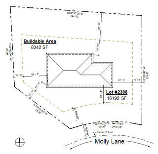
A long time fellow Revit traveler reached out to me via Revit Lifeline last night asking about zoning clearance ideas. Where he lives and works they want designers to demonstrate the building is not too tall. They also want them to prove it doesn't extend into a zone that leans back into the site. All in all the code reduces the size of the building that can be built on any given property that falls under its jurisdiction.
I have heard and read about this concern many times over the years. But in response last night, I mocked up a quick example to see if it met his needs (waiting to hear back). I thought, "Blog post? I just posted something the other day...don't get carried away. Yeah, but you've only posted like twice this year slacker! So a blog post it is then..."
Here's a few images to ponder first. Pretty fancy house design eh? Doors and windows are so last century. I CAN design YOUR next home, just call when you're ready...operators are standing by.


The upper surface is a thin floor which is manipulated through Dynamo and Shape Editing. Lauren Schmidt's LandArchBIM blog is a very nice source for land techniques and I stole her graph ideas in this post to make it. Her post explains the technique relies on a sub-region to match whatever hardscape shape (property boundary in this case) is necessary. I used the floor's offset parameter to move it up above the surface by the zoning height required.
The front and back property boundary clearance requirement is built with a railing and profile. The fact that railings can be hosted by toposurface now opens this door wide. The surface form might not lend itself to a nice clean railing though, mileage will vary. You can see the rear railing is a little deformed in a couple spots. I built parameters into the profile so I could (using types) vary the height of the angle portion, change the angle, change the height above property (spring point of the lean) and the thickness of the railing.
I created a specific material to assign to it all so it can be mostly transparent.
My example is admittedly simplistic. How many property boundaries are really a simple rectangle? Pretty rare, about as rare as a purple unicorn that uses Revit? A front or rear boundary that has arcs and many segments will probably pose some issues creating a hosted railing. I can imagine things going wrong but I'll wait until I'm dealing with something specific to worry about that.
The file I mocked this up is in Revit 2020.2 and the dynamo graph (link has both RVT and Graph) is so simple that this screen shot would help you build it nearly a fast as downloading and opening it up. That's what I did with Lauren's example. You do need the packages I've circled.

Oh, the mockup has a massing element too, you'll have to turn massing on though. At first I thought I'd sweep a profile along the property edge defined by the upper surface. After I did that I thought of the railing. The learning curve is much less steep for a railing than massing, bonus being much faster too.
Decided to add a couple more images. I realized that I could have turned off the sub-category Interior Edges for Floors to hide the tessellation in the other images. It also occurred to me that another railing and profile configuration could deal with the top. I just created another type from my existing profile family to make it a 90 degree railing. A separate wide profile without a vertical portion would provide just a top surface. The floor and railing approach don't result in the same surfaces but within reason? If reason can be applied to a zoning requirement?


Here's both visible...

I have heard and read about this concern many times over the years. But in response last night, I mocked up a quick example to see if it met his needs (waiting to hear back). I thought, "Blog post? I just posted something the other day...don't get carried away. Yeah, but you've only posted like twice this year slacker! So a blog post it is then..."
Here's a few images to ponder first. Pretty fancy house design eh? Doors and windows are so last century. I CAN design YOUR next home, just call when you're ready...operators are standing by.


The upper surface is a thin floor which is manipulated through Dynamo and Shape Editing. Lauren Schmidt's LandArchBIM blog is a very nice source for land techniques and I stole her graph ideas in this post to make it. Her post explains the technique relies on a sub-region to match whatever hardscape shape (property boundary in this case) is necessary. I used the floor's offset parameter to move it up above the surface by the zoning height required.
The front and back property boundary clearance requirement is built with a railing and profile. The fact that railings can be hosted by toposurface now opens this door wide. The surface form might not lend itself to a nice clean railing though, mileage will vary. You can see the rear railing is a little deformed in a couple spots. I built parameters into the profile so I could (using types) vary the height of the angle portion, change the angle, change the height above property (spring point of the lean) and the thickness of the railing.
I created a specific material to assign to it all so it can be mostly transparent.
My example is admittedly simplistic. How many property boundaries are really a simple rectangle? Pretty rare, about as rare as a purple unicorn that uses Revit? A front or rear boundary that has arcs and many segments will probably pose some issues creating a hosted railing. I can imagine things going wrong but I'll wait until I'm dealing with something specific to worry about that.
The file I mocked this up is in Revit 2020.2 and the dynamo graph (link has both RVT and Graph) is so simple that this screen shot would help you build it nearly a fast as downloading and opening it up. That's what I did with Lauren's example. You do need the packages I've circled.

Oh, the mockup has a massing element too, you'll have to turn massing on though. At first I thought I'd sweep a profile along the property edge defined by the upper surface. After I did that I thought of the railing. The learning curve is much less steep for a railing than massing, bonus being much faster too.
Decided to add a couple more images. I realized that I could have turned off the sub-category Interior Edges for Floors to hide the tessellation in the other images. It also occurred to me that another railing and profile configuration could deal with the top. I just created another type from my existing profile family to make it a 90 degree railing. A separate wide profile without a vertical portion would provide just a top surface. The floor and railing approach don't result in the same surfaces but within reason? If reason can be applied to a zoning requirement?


Here's both visible...