Showing posts with label Voids. Show all posts

Thursday, July 13, 2023

Phasing and Replacement Windows

Over the years people have often complained about trying to document replacing existing windows with modern windows but maintaining the existing opening. This means swapping windows with families that are the exact same size. This is related to the wall that Revit creates to infill a wall that has a demolished window. You may have encountered this warning message?


That message appeared when I attempted to place new windows in the New Construction phase after demolishing the existing windows first. I was careful to set up views assigned to different phases and phase filters so there wouldn't be any display conflicts.

I got interested in this issue again recently because of a thread at the Autodesk User Forums for Revit Architecture. A fellow member was sharing how much trouble Revit has been giving them trying to do this kind of work. After some back and forth I narrowed it down to one window family and another member realized that family uses a void to cut the hosting wall in the family itself versus the usual opening.

This led me to write some hypotheses for testing purposes. I wrote:

Hypothesis A: Within phasing we can replace Existing Window A with New replacement Window B using the exact same sizes (same size opening dimensions) IF they both use an OPENING in the family to cut the host.

Hypothesis B: Within phasing we can replace Existing Window A with New replacement Window B using the exact same sizes (same size opening dimensions) IF they both use a VOID in the family to cut the host.

If either of the above are false then...

Hypothesis C: Within phasing we CANNOT replace Existing Window A with New replacement Window B using the exact same sizes (same size opening dimensions) IF one uses an OPENING and the other uses a VOID, in the family, to cut the host.

I did some testing using the latest release of Revit, 2024.1 and I determined the following:

Hypothesis A is TRUE
Hypothesis B is FALSE
Hypothesis C is neither

I find that I can replace a Void based window with an Opening based window but not the reverse. Also any alterations to the hosting wall in the project; such as length adjustment, or top/bottom offsets, attach/detach will place the void type window at risk of being deleted. Weirder still is that it might not delete all of them, one or more.

It seems that the short answer is: eliminate window families that use a void to cut the hosting wall IF you intend to place identical sized windows in phased projects; to demonstrate existing window replacement without altering the existing openings. Windows created this way will not work for this task. A logical next hypothesis is to anticipate similar behavior in door families.

I speculate that this warning happens because an opening cuts fully through the host while a void (or combination of voids) might cut more and/or less of the host as it travels through it. I suspect that the infill wall can't abide the shape a void might create and that in turn means a void won't be viable as a window to alter the location of the infill wall. I think it's similar to curtain walls only supporting non-rectilinear panels with the system panel families.

I'd love to hear that the developers will test this against their own experience and expectations. I know that a lot of people rely on voids to shape the opening in a host wall to match a variety of actual construction techniques for openings. To eliminate voids in families as an option for this kind of project (replacement windows (and doors?)) is not ideal. They'd probably have to revisit the entire logic of infill elements where demolished hosted elements occur. Perhaps leave it up to us to fill in holes?

Tuesday, January 07, 2014

Voids and Material Orientation

When we use a void to cut a solid sweep it will affect the orientation of a material applied to it. Here's a sweep that is not cut and has a wood grain material assigned to it. I've got a void poised to cut it.


Here's the orientation of the material after using Cut Geometry.


This happens to a sweep but not an extrusion. The material sort of flashes when Cut Geometry is used but it doesn't change the orientation of the material.

If we create a Revolve solid and apply a material it will look like this when we use the End Angle setting of 180 degrees (or 360).


When we change the angle to 45 degrees the material orientation changes.


Then this happens when we apply a void using Cut Geometry, it fixes the orientation. Well it fixed the orientation of the "dome", not the "steps".

Quirky squared by subtle

Tuesday, March 12, 2013

Blends have Two Sketches

From the been there done that department I bring you a little reminder, Solid and Void blends have two sketches; a base and a top. It's pretty common to see two sketches in the base and the user wonders why they can't move on to the top sketch. When the blend process starts Revit is thinking "base", regardless of the orientation of the blend you are making. How can you tell? Easy, there is a button for Edit Top.


That can only be appropriate if Revit thinks we are working on the base. There isn't even a button for Edit Base until after you click Edit Top.


Once you have two complete sketches, each in their own "world" (Base and Top), you can Click the Green Check mark for Finish Edit Mode. If you need to revisit one or both of the sketches you'll find you can go straight to the Base or Top Sketch via separate buttons, just have to select the form first.


Remember, two sketches, two, two are better than one or twice as nice.

Tuesday, February 26, 2013

Voids Voids Voids

If you read through Autodesk documentation for Revit and the best practices document that they published some years ago you'll find casually mentioned recommendations to "avoid voids" because they will negatively impact performance. That turns into a conversation overhead later, "Never ever use voids in families!!" Hmmm...

Recommendations are wonderful, wonderful when they actually mean something meaningful. A warning like don't use more than six voids in a family. That's specific, I better not use more than six voids or something bad will happen to me, and my project. Then again I might just get wild and create families with seven voids just to make other people mad and drive project performance into the gutter?

I've read and heard similar warnings and recommendations for using formulas, "Avoid using too many formulas in your families". Is eight too many or seven hundred? I'm guessing seven hundred is worse but what about twenty five or forty five. Have we crossed into unsanctioned and untenable content now?

I'd love to see more practical recommendations that quantify things better. I seriously doubt a family with several voids is really going to harm a project, even if there are five hundred copies of the family in the project. I suppose we need to turn the Revit "masses" loose and test all kinds of situations to come up with more specific recommendations?

In the meantime I'm going to keep being careful to avoid voids all while wondering how many voids to avoid...

Thursday, March 29, 2012

Party Wall Doors

You know the doors that are in hotels that pass between rooms. They make it easy to rent two rooms side by side, one for kids, one for the parents...or co-workers traveling to a meeting etc. I got a question via email asking how to approach this. The issue expressed was that Revit won't let you put two doors on top of each other. They want to list two doors in the schedule (one for each side) so the more or less obvious solution of showing both panels and swings in one family didn't cut it.

One solution is to edit the door family and eliminate the Opening element and replace it with a void instead. This allows you to adjust the depth of the void so it only cuts one half of the shared wall. Place two doors and align them...voila, done. If you make this an instance parameter driven option your regular single flush door type could pull double duty, cutting all the way through a wall or only half way.


Another approach could be a single family that uses two nested (and Shared) families. The door could be assigned to the Generic Model category so the assembly doesn't schedule in a door schedule, the nested shared doors (assigned to the door category) do instead. Alternatively the category could be assigned to doors too but you'd either have to filter out the assembly or the individual doors because you'd have an "extra" door.

Whatever solution we use we do have to consider how "we" schedule doors and how the product is dealt with by a manufacturer. Since the frame has to built to accomodate two panels it might actually be better or correct to create a single door family that just happens to have two panels. Everything is a bit trickier the deeper you look at the question, at least when you aren't just concerned with what a door looks like in a plan view drawing.

Tuesday, August 23, 2011

Array the Void Instead

Voids and solids interact in a specific order according to when each are created. I wrote another post to describe this in the past (July 2006). When you create an array of solids this can create a problem if your family isn't built with the notion of a maximum number of solids present at design time.

For example imagine slats that provide closure beneath a porch. If you design a family to array the slats you need to decide how many is enough. If you don't and you ask for more slats than your void(s) are able to cut you'll get new slats that aren't altered by the void. As the earlier post explains, this is because voids don't cut (not automatically) solids that get created after they are.

Quite some time ago (May 2005 actually) this came up in the form of a question at AUGI. The inspiration for the thread was Jerry's nicely modelled Queenslander style house and porch detail.


The trick to get this to work is reversing the logic. Since voids can't cut later solids, array the void instead. A new void will cut an existing solid automatically as long as the void and solid intersect when its sketch is finished. This means adding a new void to the array cuts the existing (only) solid, yay!

The "slat" is a single solid "sheet" and the voids array to remove/create the "spaces", to turn the sheet into "slats". There is an arc beneath the slats to carve off the bottom of the slats so they all are cut to create a uniform arc. The arc will flex when the width changes and there is a chord height parameter. It uses a reference line and the first void is created on the flat plane of the reference line. Then the array includes both the void and the reference line.

Here's what it looks like in use.


You can download the proof of concept family at AUGI in the thread or from HERE.

Tuesday, May 10, 2011

Dept. of Subtle - Opening Transparent in Elevation or 3D

Quick one tonight. The opening element in window families is designed to offer either transparent or opaque behavior when seen in elevation/section views. Normally we like to "see" through glass in 3D views so we can see inside the building. In elevation/section views however seeing the "innards" of the building might be really confusing to the reader. This subtle setting determines how the opening should behave in either condition.


If you want to see through your openings in elevation, check the option for Elevation. It's usually not checked which is why you can't see through them. If you'd rather obscure them in a 3D view to then remove the check for 3D.

In the past we couldn't have more than one Opening element in a single family so we often removed them and used a void instead. I find in 2011 and 2012 that Revit doesn't mind multiple openings in the family. You can't however have a void and an Opening in the same family, one or the other. To be more accurate you CAN create a void but you'll get this message if you try to CUT the host with the void.


Wednesday, April 15, 2009

Revit 2010 Fixes Floor Void Issue

I'm happy to report that an earlier post that I made about floors and void elements is no longer an issue with the new release of Revit Architecture 2010 and the other versions too.

In the new release a floor will show a reduction in volume when an in-place void, a face based void family or a floor based void family is used. An undocumented fix that is welcome! Thanks!

Thursday, July 20, 2006

Which Came First? The Solid or the Void?

...and the other short story...why did the solid cross the road? Sorry I digress.

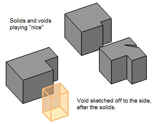
So you're making a family and you made this solid and then you made this void and Revit cut away the solid just fine. Now you make a new solid and the void acts like it doesn't know it is there even though they intersect. Voids only automatically cut solids that came before, not those that followed. So...when a void doesn't cut a solid because of the order you created them, just use Tools > Cut Geometry and tell Revit to cut em!Worth mentioning, if you create a void and it doesn't intersect with the geometry of the earlier solid(s) when you finish the sketch, when you drag the void so it does intersect with the solid, it won't cut automatically either. Even if the solid was made earlier than the void. So again, Tools > Cut Geometry to the rescue.aaah...all better now...