Showing posts sorted by relevance for query automatic sketch dimensions. Sort by date Show all posts

Monday, April 09, 2012

A Small Collection of Family Editor Advice

I included the following tips and advice (edited a little in this version) in a door tutorial I wrote for my Autodesk University 2005 lab called "Autodesk Revit Building Family Editor: From the Beginning". It wasn't necessarily a really better door as it was a chance to explore a number of different techniques using the family editor. Such as nesting families, Variable swing features 2d/3d, Alignment for adjacent walls and creating a variable multi-lite panel. You can download the PDF HERE.

General Advice and tips
  1. Use snaps and snap overrides
  2. With dimensions and align/lock make sure you select the correct element, as a reference, that you intended.
  3. Use temporary hide/isolate to make sure only the objects you want to reference are visible.
  4. Alter dimension style(s) so it/they work(s) better for laying out your family, remove extension line offset, decrease text size etc.
  5. Dimension only to reference planes, align/lock solids/voids to reference planes
  6. If you ignore #5, don’t do both “inside the sketch” and “outside the sketch”
  7. Don't move the "origin", check the location of the origin by importing a dwg with linework representing 0,0, and use “Origin to Origin” if you think you did. A little background, if you move the reference planes defining the origin you will think the placement origin is moved. In fact the reference planes don't really define the origin anymore because Revit maintains the original origin is actual the internal 0,0 for placement. [This was a bug and has supposedly been fixed in the releases following 2005.]
  8. Don't use "-" in parameter names because it turns into a minus if you use the parameter in a formula, in fact don't use any characters that double as "math" symbols.
  9. Change the scale of the view to make it easier to constrain, select geometry.
  10. Be sure to test the family at various scales including for line weights, graphic performance and particularly if nested annotation are included.
  11. Add additional types to the host in hosted families. This makes it faster to test for different host thicknesses.
  12. Don't define materials in families, define material parameters instead (or possibly sub-categories) as much as possible so materials can be assigned in a project, where they really matter.
  13. Don't include parameters in families that don't change geometry, instead put them in project templates and apply them to the categories they affect.
  14. Don't dimension objects inside a sketch and then constrain the object outside the sketch, either all in or out. The exception to this is the depth of an extrusion which you can constrain outside of a sketch because you can’t constrain it with dimensions elsewhere. It is safer to align/lock to reference planes.
  15. Angles and arcs are hardest to constrain because Revit deals with them using orthogonal dimensions. Examine the Automatic Sketch Dimensions (ASD's see below) to see how they constrain endpoints of lines and arcs. Save them for last and use Hide/Isolate and remove unnecessary objects from view so it is easier to ensure you constrain the right parts.
  16. Window and Door families use the cut plane (view range) defined in the family, not just the project's view setting for view range.
  17. Make a system type parameter into an instance parameter, select dimension with a label in view, check instance parameter in option bar.
  18. Shared families can only pass (forward) instance based parameters
  19. Voids don't allow visibility on/off or level of detail
  20. Mirror tool does not pass along locked relationships, need to establish them for each copy.
  21. (added) Remember Revit is work plane focused, use reference planes and name them. Then use them wisely. There is a head and tail and they define positive and negative depth values for solid/voids.
  22. (added) Reference Lines are for angular relationships. Reference Planes are NOT. Reference planes don't have real endpoints, they are infinite in length but have grips so we can control how much we have to see.
  23. (added) The conceptual massing environment (CEA) is VERY different from all other component family editing you'll do.
  24. (added) A family doesn't "have to" be hosted if it doesn't "need" to "cut" the host or in other words, create a hole in the host. It must be hosted if it does.
  25. (added) Build "bones" first, then add "muscle" and finally the "skin".
    • Bones = Reference planes/lines
    • Muscle = Dimensions/parameters
    • Skin - solids/voids and model/symbolic lines
If you are interested in some additional reading and curious about Automatic Sketch Dimensions (ASD's), these are some earlier posts.

Locking Stuff (January 2011)
Railing Encore (August 2008)

Tuesday, April 04, 2006

Automatic Sketch Dimensions

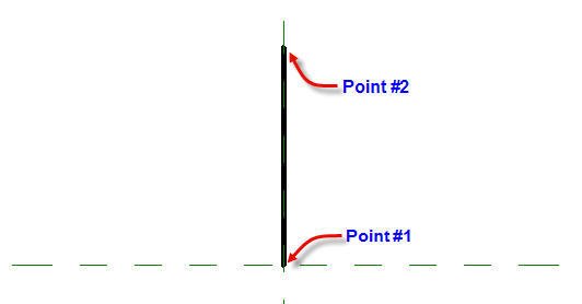
Did you know these are lurking in every family that you build? As soon as you add a parameter to a dimension Revit starts using them. Take a look at this simple sketch, just a Model Line drawn over the vertical Reference Plane called Center(Left/Right).

Nothing special to see eh? Just notice the direction of the line for later okay?

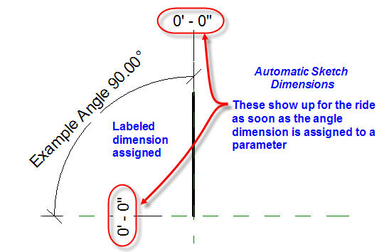
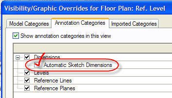
Now take a look at the same family with a parameter added to the angular dimension between the Model Line and the horizontal Reference Plane.Never seen them you say? Well you have to know when to look! Or at least how to turn them on! They are off by default typically. When you are editing a family, click the View menu, choose Visibility/Graphics and click the Annotation Categories tab to see where they are hiding.

So what are they doing? Revit uses them to infer intent once we start using parameters and labeled dimensions. If Revit does well, we get automatic behavior from our family with a minimum of effort. When it doesn't we get less predictable behavior. It is important to tell Revit what we want when this happens. Reviewing these Automatic Sketch Dimensions can help us decide what parameters we really need to add to eliminate any confusion.

A short search of Revit's help documentation will yield a nice graphical example of how these work. Try here>>

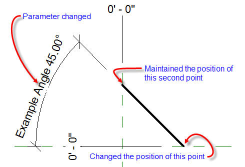
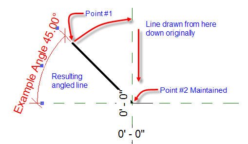
A subtle related issue is sketching lines directly on a Reference Plane. The first image showed the line drawn from the intersection of Reference Planes, up. This image shows the results of the parameter driven change.Reversing the direction of this line, drawing it from the top down toward the intersection yields better results perhaps?It is more reliable, or at least more predictable, to sketch lines, that are intended to be flexed with labeled angular dimension, away from Reference Planes entirely. Sketch them at an angle instead.

Monday, November 11, 2013

Adjusting Automatic Sketch Dimensions

When we are working on families Revit hides Automatic Sketch Dimensions (ASD's) from us unless we use Visibility/Graphics to turn them on (Annotation Categories tab). Revit guesses are often close enough when it creates ASD's. For example the profile of a skirt/apron beneath a table top is adequately constrained by the ASD's in this image.


When I add another sketch inside the first to define the thickness of the skirt/apron Revit guesses correctly again. If you select ASD's Revit doesn't let us delete them. If we add our own dimensions and either assign a parameter or invoke the EQ or Padlock constraints Revit will remove the corresponding ASD.


If Revit places a ASD incorrectly we can change what it's referencing. Select it and click on the witness line grip (dot icon) and drag it to a correct reference. For example, in this image Revit guessed that it's more important to reference the Center (Front/Back) Reference Plane. That's not what I had in mind.


In the little bubble of the image I've revised it so that the ASD is referencing the correct elements. Revit will respect this change unless we change the family and cause it to revisit the constraints, such as deleting a form or altering an existing sketch. Remember to keep an eye on ASD's.

Tuesday, May 13, 2014

Where are the Constraining Dimensions

When you edit a family that someone else created you may encounter a situation where the constraints that control it aren't readily visible. Yeah, it could even happen to you with content you created. These are a few things to consider when you start hunting for them.

Inside the Sketch - It is possible to add dimensions and parameters to control solids/voids while editing their sketch. If that's been done you won't see them unless you edit the sketch for that solid/void.

Associate Family Parameter - The little sneaky gray button (that has a tool tip since 2014) allows us to constrain some things without an actual dimension in canvas. We just connect the dots between the parameter of the form with a parameter.

Automatic Sketch Dimensions - These kick in when you start creating parameters and elements without tying them to anything specific. Revit guesses what you have in mind. They'll usually only be visible while you are editing a solid/void. They are definitely off by default in Visibility/Graphics. You'll find them under the Annotation Categories tab. I've written about these in the past.

Choice of View - Sometimes the dimension isn't in a view that we'd expect it to be in. For example the stock door template has the width parameter in an elevation view instead of the plan view. I certainly wouldn't expect to find it there. I try hard to put X/Y oriented dimensions in plan views and Z oriented dimensions in elevations, usually Front but occasionally Right.

Visibility/Graphics - Sometimes dimensions are just turned off in the family's views.

2014 Revit OpEd

Saturday, August 29, 2009

Automatic Sketch Dimensions

If you say, "What are those?" then this post is for you. Actually this video is for you. I've posted or mentioned them in other posts before too. You can watch the VIDEO HERE or listen and sort of watch below.


To summarize, Automatic Sketch Dimensions are added to your family when you add constraints in the form of parameters and dimensions but don't constrain the symbolic lines and the sketches for the 3D geometry that you create.

Thursday, April 10, 2008

Revit MEP Air Terminal - Troubleshooting

I received an email from client asking for a little assistance with an air terminal family. Apparently the diagonal line they wanted to indicate that the terminal is a "return" wouldn't play along when the family changed size.

Recently I was in Houston and David Baldacchino (Do U Revit? blog) and I had a chance to hang out. He told me about a new (new to me) video capture tool called Jing Project by Techsmith (makers of my favorite screen capture tool SnagIT) that allows you to do screen capture to video or images as well as audio. Then you can easily post the video on Screencast. This post is as much a test as an example of troubleshooting a family.

The issue came down to this. Revit constrains elements orthogonally. The diagonal symbolic line is constrained to the reference planes, not the edges of the neck opening that they wanted it to "follow". The video describes the process of using the Automatic Sketch Dimensions (ASD's) that Revit applies when we do not explicitly add our own dimensions or lock padlocks, for example. The ASD's will do the job nicely as long as well "tell" them what is important to us.

Here's a link to the video: (embedded it is too big to view on the blogger screen)

Download it HERE. (3.75mb)

Thursday, April 02, 2009

The Family Editor: Bones, Muscle & Skin

I have heard the term "bones" and phrase "build the bones" used in the context of the family editor in the past. In fact some of the earlier Revit Technology Corporation (RTC) and Autodesk Family Editor documents have used the term too, perhaps for the first time even. Lately over the last year or two I've been expanding on the metaphor.

Bones = Reference Planes
Muscle = Dimensions, Labels/Parameters, Automatic Sketch Dimensions
Skin = Solids/Voids and Symbolic Linework

If you properly define the "bones" first and then connect the "muscle(s)" to them you'll find that your "skin", once anchored to the bones, will go wherever the muscle tell the bones to go. I just picture my arm and in fact I usually hold it up and move it at the elbow while I mention it in classes. A properly defined family will behave as consistently as your arm does, unless you manage to do it harm skiing?

Too clinical? Squeamish? Sorry!

Saturday, August 16, 2008

Railing Encore


I dug up another railing example that I've had kicking around for a few years now. It was inspired by a client who was modeling an addition to an existing school building that had this pattern on its stairs already. There was some pressure to use this in the new work as well.


If you look really close you'll see the railing is "floating" on a cushion of air. The exercise was about making the baluster, not worrying about posts. It was quite a lesson in Automatic Sketch Dimensions.


These are the "secret" dimensions that Revit uses to manage the position of your family's parts when you don't take the trouble to be specific. You don't know they are there? That's because they are off by default in all family templates. You can find them under the Annotation Categories Tab in Visibility/Graphics. I wrote this POST about them in April of 2006. But I digress.

I've posted the file so it can be downloaded if interested.
You can watch a video about ASD's about this too.

Download Example Project File HERE.

Saturday, August 18, 2012

Constraining Tangents

I read a post at AUGI the other day which originated with a post in July (2012). The goal was to create a rebar shape for detailing purposes. A few people offered ideas even a file or two. It seemed simple enough to do but digging into it I found several variations in a theme to constrain the geometry works. Here's my exploration captured in these images.

This image is the overview of what parameters are desired: Length, Depth, Fillet Radius and Angle.


Simply sketching the "bones, muscle and skin" is often enough. In this situation, as you flex the parameters the tangent arc starts to distort eventually. Revit does not understand how to respect the arc and line end points, keeping the lines tangent to the arc. That means it needs more constraints. One way to see how well Revit understands our intentions is to turn on Automatic Sketch Dimensions (ASD's).


When you see little blue dimensions you know that Revit doesn't understand you, you need to be more explicit. If you look closely at the very last image you'll a single ASD (showing 0'-0") along the vertical reference plane. Unfortunately just getting rid of ASD's with better constraints isn't a guarantee for success.

This image is the messiest solution, I used a circle to "see" how the geometry moved around and then used it to create enough constraints so that it flexes correctly.


This image is a variation on the previous theme but using Reference Lines as the underlying "bones", pretty "messy" too eh?


This is yet another approach. I used a pair of model lines (assigned to Invisible) to govern the location of the arc and line endpoints.


This final one is the simplest in appearance but it has two line segments instead of one along the angled segment. I noticed that connecting the end of the angled line would break the relationships. I tried pulling the end of the line away from the end of the arc, leaving them apart, and flexing geometry worked. That led me to try a second line between the end of the arc and the end of a smaller line and it worked too. Not obvious at all. It also means that the family will break if one of these segments is flex too far, assuming the changes result in a zero length segment. The family will break easily anytime the angle entered creates a zero length segment of the vertical line too (all of them, not just this one). Fragile but the family works.


In the thread at AUGI the member that started it all replied that he figured out how to solve it after reading a post at BIM & BEAM. I tried using the formulas as well but found it was necessary to play the "two lines instead of one trick" to get it to behave.

If you'd like to play around with the families I created doing this I've posted them HERE. I'd be interested if anyone can find simpler solutions.

[Edit 08/20/2012: Alfredo Medina shared a solution at the AUGI thread that uses formulas to define the relationships consistently. CLICK to watch his video of it flexing. CLICK to download his family. (You'll need to log into AUGI to download it most likely)

Tuesday, January 11, 2011

Locking Stuff

I've written about Automatic Sketch Dimensions before, April 2006 and August 2009. I'm bringing them up again because every now and then I run into someone who doesn't know about them and thinks that Revit is a bit magical, it just seems to know how to keep things in place, groovy! I recorded this Video awhile back but I'm dredging it up again just in case a reader missed it before.

Unable to display content. Adobe Flash is required.